Endoscope

a technology of endoscope and endoscope, which is applied in the field of endoscope, can solve the problems of increasing the number of components, affecting the quality of endoscope, so as to reduce the size and cost

Active Publication Date: 2017-11-28
PANASONIC I PRO SENSING SOLUTIONS CO LTD
View PDF38 Cites 795 Cited by
  • Summary
  • Abstract
  • Description
  • Claims
  • Application Information

AI Technical Summary

Benefits of technology

[0011]The present invention has an object to provide an endoscope with a reduced size (for example, the thinning of the exterior diameter of a distal insertion part) and a reduced cost.
[0014]According to the present invention, it is possible to provide a miniaturized and cost-reduced endoscope.

Problems solved by technology

Therefore, in some cases, the oral endoscope is likely to touch a tongue's root when being inserted, thereby causing the surgical target person to suffer nausea or a feeling of dyspnea.
Therefore, it is difficult to observe the inside of the human body by inserting the endoscope 503 into vessels or holes having very small diameter, for example, such as blood vessels of the human body.
Since the exterior cylinder 535 is required, the number of components increases, and the cost increases.

Method used


Image

  • Endoscope
  • Endoscope
  • Endoscope

Examples


first embodiment

Basic Configuration Example

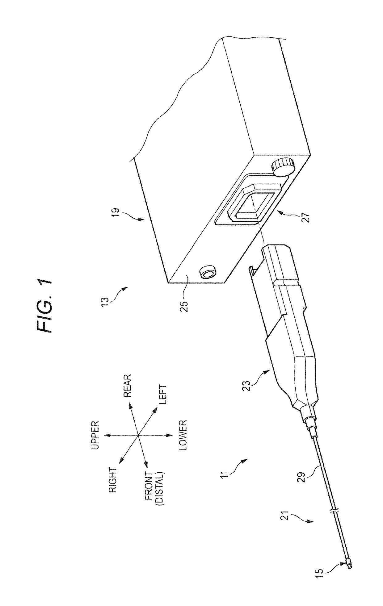
[0062]FIG. 1 is an overall configuration diagram illustrating an example of an endoscopic system using the endoscope according to each embodiment. FIG. 1 illustrates a perspective view of an overall configuration of an endoscopic system 13 including an endoscope 11 and a video processor 19.

[0063]A direction used for description herein is indicated in accordance with description of a direction in each drawing. Here, “up” and “down” respectively correspond to a top and a bottom of the video processor 19 placed on a horizontal plane. “Front (distal)” and “rear” respectively correspond to a distal side of an insertion part 21 of an endoscope main body (hereinafter, referred to as the “endoscope 11”) and a proximal side of a plug part 23 (in other words, the video processor 19 side).

[0064]As illustrated in FIG. 1, for example, the endoscopic system 13 is configured to include the endoscope 11 serving as a medical flexible endoscope, and the video processor 19 w...

first configuration example

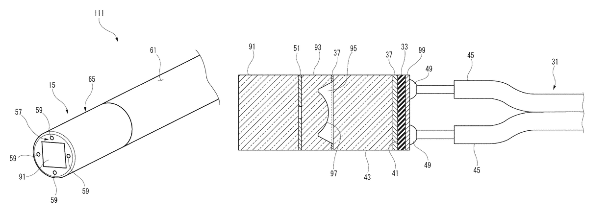
[0075]The endoscope 11 according to the first configuration example includes the lens unit 35 that accommodates a lens in a lens support member 39, the image sensor 33 whose imaging area is covered with the sensor cover glass 43, the bonding resin 37 that fixes the lens unit 35 and the sensor cover glass 43 in which an optical axis of the lens is coincident with the center of the imaging area, and the transmission cable 31 that has four electric cables 45 respectively connected to four conductor connection parts 49 disposed on a surface opposite (that is, rear side) to the imaging area of the image sensor 33.

[0076]Multiple (three in the illustrated example) lenses L1 to L3 formed of an optical material (for example, glass or a resin) and an iris 51 formed by being interposed between the lens L1 and the lens L2 in a state where all of these are close to each other in a direction of the optical axis are incorporated in the lens support member 39. The iris 51 is disposed in order to ad...

second configuration example

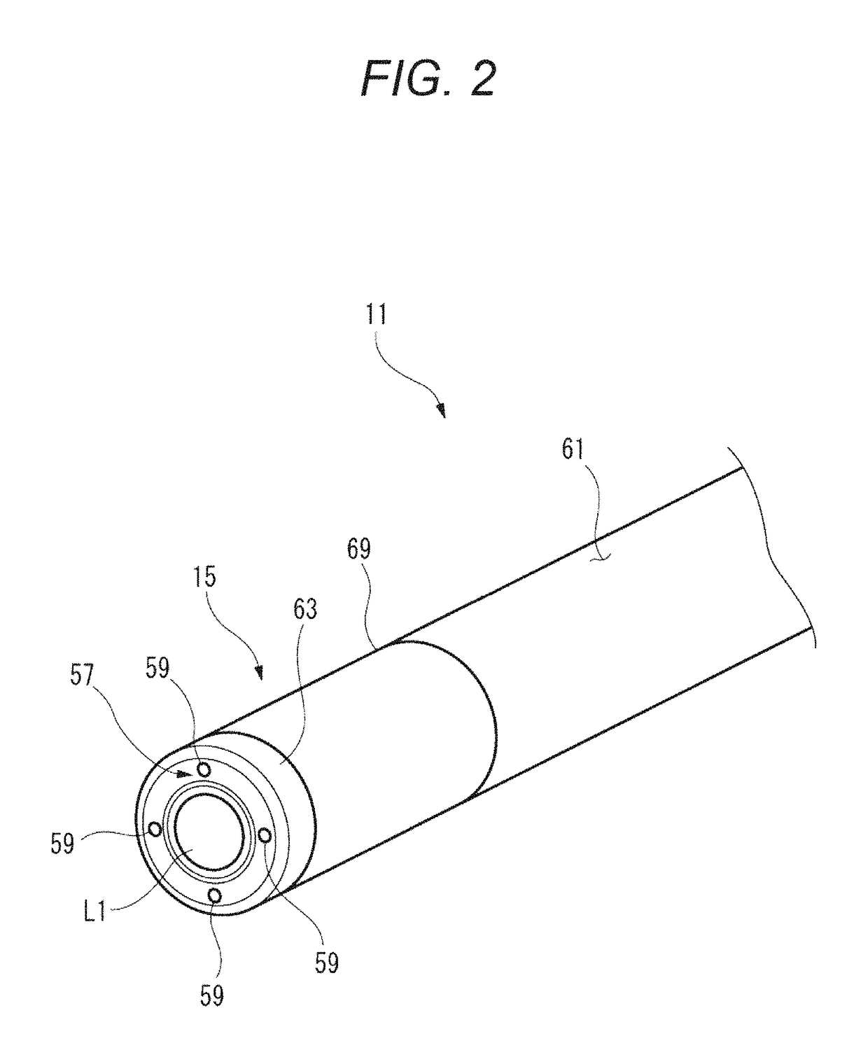
[0089]According to the endoscope 11 of a second configuration example, in the endoscope 11 according to the present embodiment, the maximum exterior diameter Dmax of the distal portion 15 can be formed within a range from a limited diameter to 1.8 mm which corresponds to a diameter of a circumscribed circle of a substrate of the image sensor 33 which can be diced.

[0090]In the endoscope 11 according to the present embodiment, as the image sensor 33 whose cross section in the direction perpendicular to the optical axis has a square shape, those which have one side dimension of 1.0 mm are used. In this manner, in the endoscope 11, a diagonal dimension of the image sensor 33 is approximately 1.4 mm. If a light guide 57 (for example, (φ150 μm) serving as lighting means is included therein, it is possible to set the maximum exterior diameter Dmax to 1.8 mm or smaller.

[0091]As described above, according to the endoscope 11 of the second configuration example, since the maximum exterior dia...


PUM


Abstract

An endoscope includes a single lens that has a square exterior shape in a direction perpendicular to an optical axis, an image sensor that has an square exterior shape which is same as the exterior shape of the single lens, in the direction perpendicular to the optical axis, a sensor cover that has an exterior shape which is same as the exterior shape of the single lens, in the direction perpendicular to the optical axis; and a bonding resin portion that fixes the sensor cover to the single lens, The single lens is a lens which is formed in a prismatic shape. The single lens has first surface on an imaging subject side that has a plane, and has second surface on an imaging side that has a convex surface.

Description

BACKGROUND[0001]1. Technical Field[0002]The present invention relates to an endoscope.[0003]2. Description of the Related Art[0004]In the related art, an endoscope for imaging an internal state of a patient's body, and an interior of a device or a structure has been widely used in a medical field or an industrial field. In the endoscope of this type, in an insertion part inserted into an observation target, light from an imaging site is received by an objective lens system so as to form an image on a light-receiving surface of an image sensor. The endoscope converts imaging forming light into an electrical signal, and transmits the electrical signal as a video signal to an external image processing apparatus via a signal cable.[0005]For example, as for the endoscope used in the medical field, in order to reduce the burden of a surgical target person, it is important to further reduce an exterior diameter of the insertion part on a distal side inserted into a body of the surgical tar...

Claims


Application Information

Patent Timeline
Patent Type & Authority Patents(United States)
IPC IPC(8): G02B23/24A61B1/07A61B1/00A61B1/05A61B1/06A61B1/307H04N5/225A61B1/04
CPCG02B23/243A61B1/0011A61B1/00018A61B1/00096A61B1/051A61B1/0607G02B23/2469G02B23/2484H04N5/2253A61B1/07H04N2005/2255A61B1/0676A61B1/0684A61B1/307A61B1/00163G02B23/2476A61B1/00071A61B1/00112A61B1/05H04N23/555H04N23/54
Inventor HARAGUCHI, NAOYUKISANADA, TAKAFUMIHANADA, YASUYUKIHATASE, YUICHI
Owner PANASONIC I PRO SENSING SOLUTIONS CO LTD
Why Eureka
Try Eureka