
Exhaust gas clean-up system for fossil fuel fired power plant

Active Publication Date: 2017-12-05
GLOBAL CARBON EMISSIONS SOLUTIONS LLC
View PDF9 Cites 3 Cited by
  • Summary
  • Abstract
  • Description
  • Claims
  • Application Information

AI Technical Summary

Benefits of technology

The present invention is a system to clean up the exhaust gas from a fossil fuel power plant before it is released into the atmosphere. The system includes a cyclone and an activated carbon filter to remove fly ash and reduce mercury and mercuric salts by about 75%. To improve the removal of mercury and mercuric salts, a solubilizer like glycerol is added to enhance the solubility of calcium hydroxide. When the glycerol / calcium hydroxide solution interacts with the exhaust gases in the reaction chamber, mercury and mercuric salts are significantly removed.

Problems solved by technology

There have been many different arrangements that attempt to remove detrimental flue gas compositions but most of them are only partially effective in removing most if not al the detrimental exhaust gas compositions.
Many times, this is based on the extreme cost of effective types of exhaust gas removal systems.
Emissions of nitrogen oxides into the atmosphere can result in the generation of ozone in our atmosphere.
However, ozone can be a hazard to humans when it is within our habitable altitude.
Another emitted gas that is detrimental is sulfur dioxide.
It reacts with atmospheric water and causes acid rain.
Likewise, carbon dioxide creates major environmental issues when exhausted into the atmosphere and is the main cause of global warming and climate change.
Eli Gal et al is using ammonium ions to aid in breaking down the limestone to a more finite size and does not teach the use of adding a reacting compound to a reaction chamber to cause a chemical reaction to reduce detrimental elements in the exhaust gas.
However, the same detrimental gases or compounds could be introduced from other types of power plants.
These ‘bag houses’ require large amounts of floor space and also require large amounts of maintenance.
However, the activated carbon filters are still limited in that they can normally only remove about 50-75 percent of the mercury and mercuric salts from the exhaust gases.

Method used


Image

  • Exhaust gas clean-up system for fossil fuel fired power plant
  • Exhaust gas clean-up system for fossil fuel fired power plant
  • Exhaust gas clean-up system for fossil fuel fired power plant

Examples


Embodiment Construction

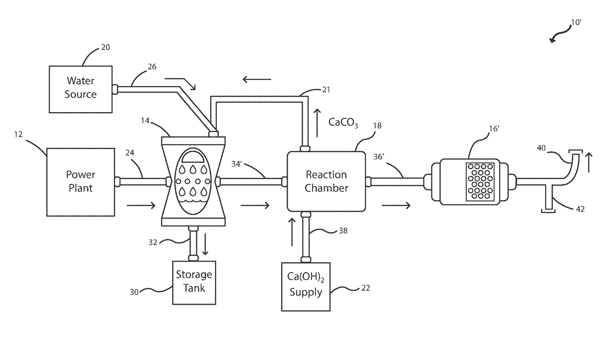
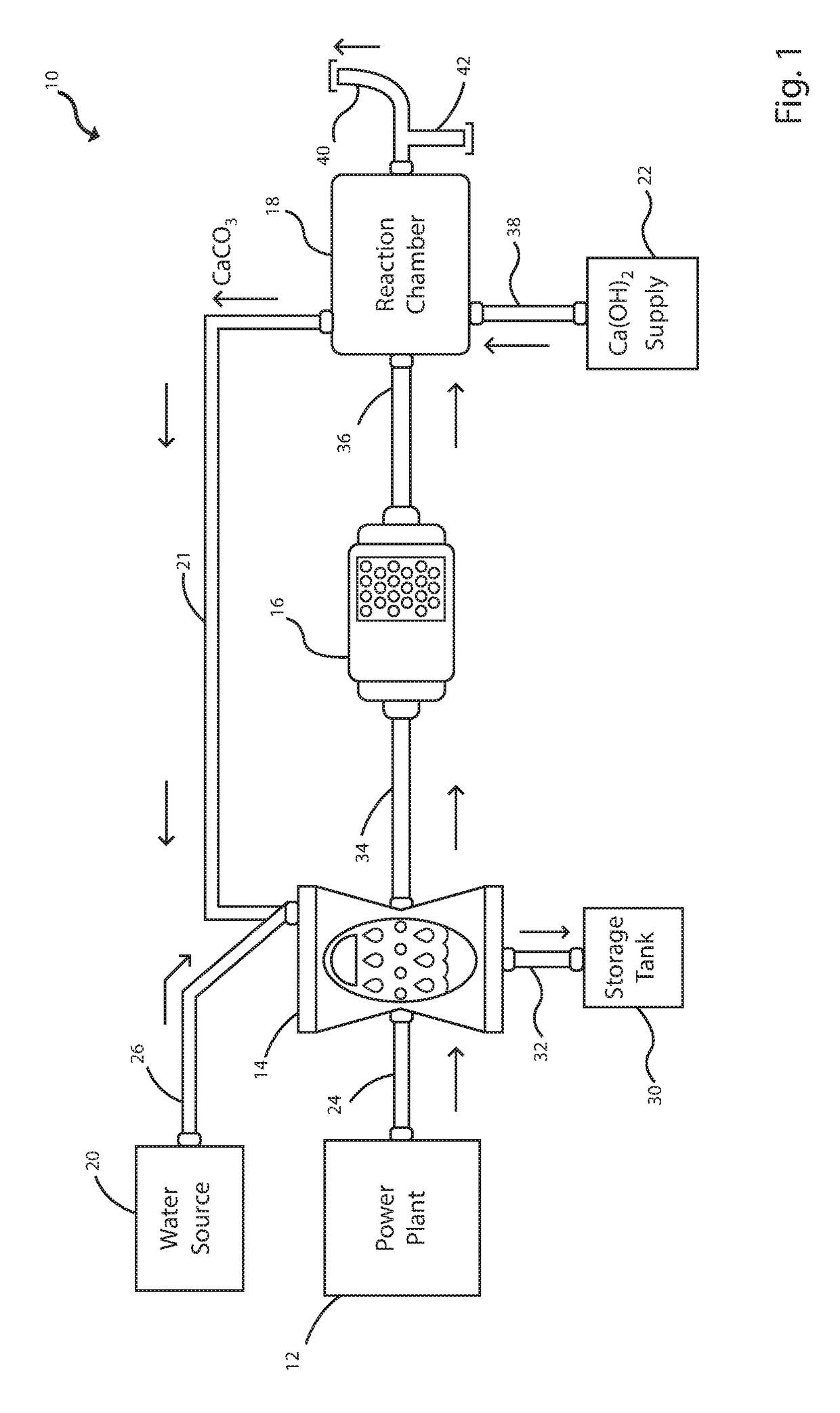
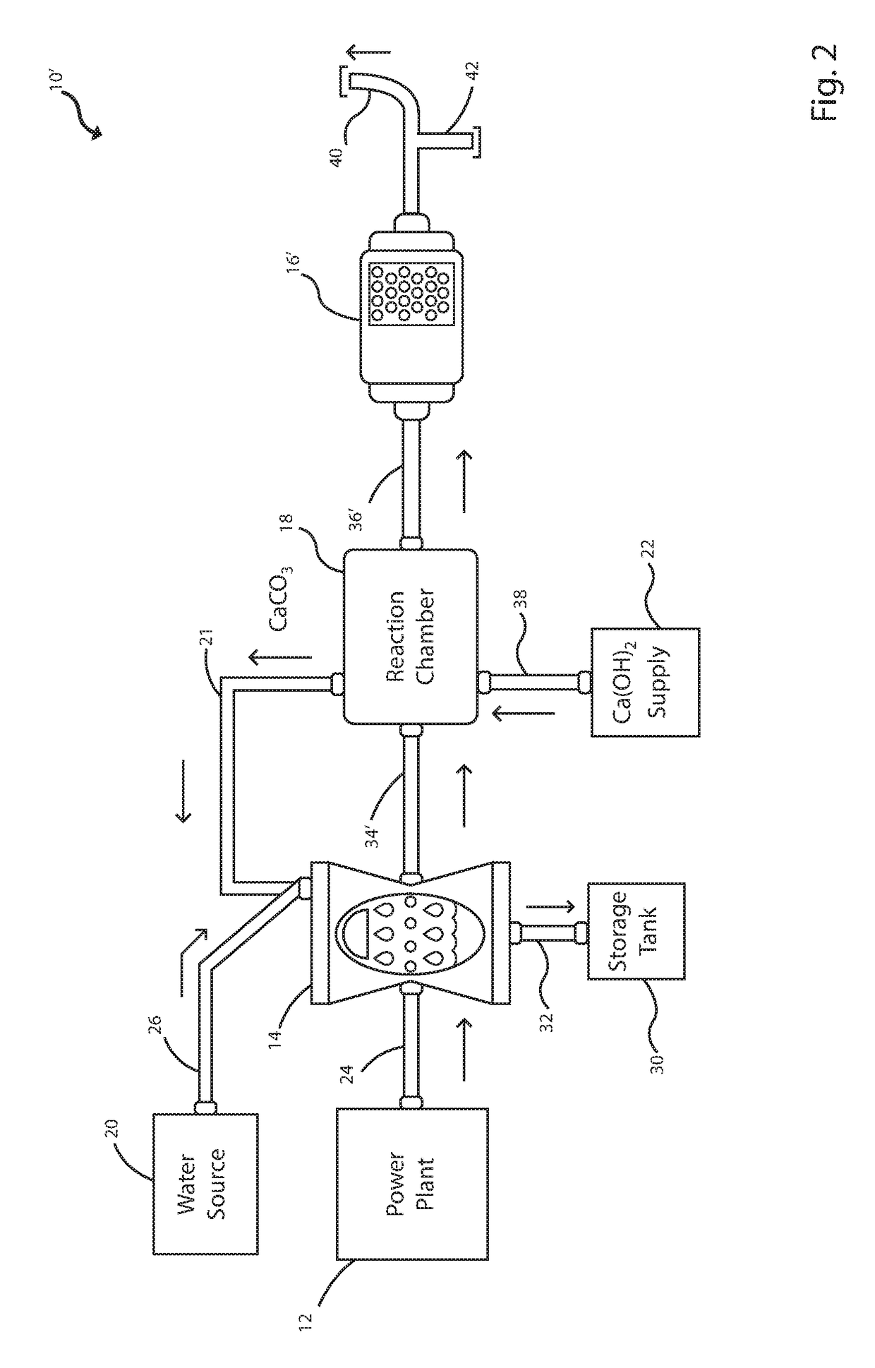
[0010]Referring to FIG. 1 of the drawings, an exhaust gas clean-up system 10 is provided. The exhaust gas clean-up system 10 is connected to the exhaust of a typical fossil fuel fired power plant 12. The exhaust gas from the fossil fuel fired power plant 12 contains various percentages of water (H2O), nitrogen (N), sulfur dioxide (SO2), carbon dioxide (CO2), and nitrogen oxides (NOx). There could be minimal amounts of carbon monoxide (CO) depending on the purity of the fossil fuel being used. The gas clean-up system 10 includes a wet scrubber 14, a catalytic converter 16, a reaction chamber 18, a source of water 20, a source of a chemically produced compound connecting line 21, and a source of reacting compound 22.

[0011]The wet scrubber is connected to the exhaust of the power plant 12 by an exhaust gas connection line 24 and to the source of water 20 by a water connection line 26. The source 22 of the chemically produced compound is, in the subject arrangement, the reacting chamber...


PUM

PropertyMeasurementUnit
Weightaaaaaaaaaa
Solubility (ppm)aaaaaaaaaa
Solubility (mass)aaaaaaaaaa

Abstract

A fossil fuel fired power plant exhaust gas clean-up system is provided to remove detrimental compounds / elements from the exhaust gas emitting from the power plant to protect the environment. This is accomplished primarily by directing the exhaust gas from a fossil fuel fired power plant through both a reaction chamber containing a chemically produced compound and a catalytic converter. The final exhaust gas can now be safely exhausted to the atmosphere and only contains nitrogen gas, oxygen, water and a trace amount of carbon dioxide.

Description

TECHNICAL FIELD[0001]The subject design relates generally to an exhaust gas clean-up system that helps to remove some detrimental exhaust gas compositions and more specifically relates to a process and apparatus that processes exhaust gas from a fossil fuel fired power plant to remove detrimental exhaust gas compositions.BACKGROUND[0002]There have been many different arrangements that attempt to remove detrimental flue gas compositions but most of them are only partially effective in removing most if not al the detrimental exhaust gas compositions. Many times, this is based on the extreme cost of effective types of exhaust gas removal systems. Emissions of nitrogen oxides into the atmosphere can result in the generation of ozone in our atmosphere. Ozone is important in our higher altitudes since it helps to offset the effects of the sun's damaging rays on the earth. However, ozone can be a hazard to humans when it is within our habitable altitude. Another emitted gas that is detrime...

Claims


Application Information

Patent Timeline
IPC IPC(8): B01D53/14B01D53/80B01D53/64B01D45/12B01D46/00B01D39/20B04C9/00B01D53/75B01D53/48F23J15/02B01D53/86
CPCB01D53/75B04C9/00B01D39/2055B01D46/0036B01D45/12B01D53/64B01D53/80B01D53/48B01D53/8631B01D53/864F23J15/02B01D2255/1021B04C2009/002B01D53/40B01D53/504B01D53/8681B01D53/869B01D2251/404B01D2251/604B01D2251/606B01D2256/20B01D2258/0283F01K13/00F01K27/00
Inventor KUKU, LAI O.MATHEW, MELVINWOUDENBERG, MICHAEL P.
Owner GLOBAL CARBON EMISSIONS SOLUTIONS LLC
Learn More