Staged Z-pinch for the production of high-flux neutrons and net energy

a neutron and net energy technology, applied in nuclear targets, nuclear reactors, greenhouse gas reduction, etc., can solve the problems of plasma instabilities, many problems in fusion energy production, etc., and achieve the effects of improving stability, speeding up the rise time, and increasing power

Active Publication Date: 2017-12-05
RGT UNIV OF CALIFORNIA
View PDF0 Cites 0 Cited by
  • Summary
  • Abstract
  • Description
  • Claims
  • Application Information

AI Technical Summary

Benefits of technology

[0015]Staged Z-pinch fusion is a controlled compression and heating of a fusible material to a temperature and pressure such that fusion can begin and excess energy then extracted and the resulting neutron flux used for production purposes. The staged Z-pinch fusion may be used to produce net energy gain many times larger than the energy used to drive the pinch, Z is represents the atomic number of the element used in the liner surrounding the fusible material to be compressed. One of the features of the illustrated embodiment is the utilization of the physics responsible for producing fusion, comprising stages of shock heating and compression, and confinement of fusion alpha particles, leading to target ignition. Fusion energy production has many problems in a Z-pinch configuration with plasma instabilities are the primary limitation. When the plasma is compressed instabilities prevent the accumulation of plasma with a sufficiently high-energy density to ignite fusion.
[0040]The pulsed power driver generates a fast rise time current pulse to cause the high Z liner to implode onto the fusible target to provide a stable compression of the liner and formation of a shock front that compresses and heats the target plasma rapidly to a temperature >5 keV and a particle density >1023 cm−3.

Problems solved by technology

Fusion energy production has many problems in a Z-pinch configuration with plasma instabilities are the primary limitation.

Method used


Image

  • Staged Z-pinch for the production of high-flux neutrons and net energy
  • Staged Z-pinch for the production of high-flux neutrons and net energy
  • Staged Z-pinch for the production of high-flux neutrons and net energy

Examples


Embodiment Construction

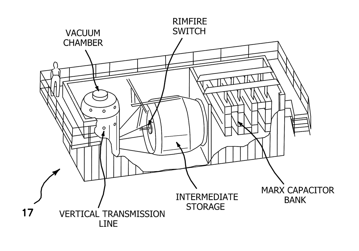
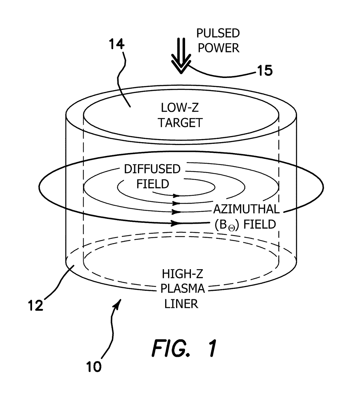
[0062]The illustrated embodiments are directed toward the production of a magnetically-accelerated, inertially-confined, high-energy-density pinch. FIG. 1 illustrates schematically the plasma load of a staged Z-pinch chamber 10, where the fusion reaction takes place. The dimensions of the staged Z-pinch chamber 10 are nominally 1-cm high×1-cm diameter. This fusible load 14 is placed at the center of a transmission line of pulsed power 15 which delivers a pulsed-electric current to the plasmas 12, 14, for example as shown in a cutaway view of a chamber 10 shown in FIG. 13. The approximate current parameters are 1 MA and 1 MV, delivered in 100 nanoseconds. To provide this power special pulsed power generators 17 are used, for example as illustrated for the University of Nevada, Reno, Zebra Facility shown in FIG. 14. Although the size of the Zebra Facility is large as shown in this illustration, in practice the pulse generator 17 can be engineered to be smaller than this by a considera...


PUM


Abstract

A fusible target is embedded in a high Z liner, ohmically heated and then shock wave heated by implosion of an enveloping high Z liner. The target is adiabatically heated by compression, fusibly ignited and charged-particle heated as it is being ignited. A shock front forms as the liner implodes which shock front detaches from the more slowly moving liner, collides with the outer surface of the target, accelerates inward, rapidly heating the target, adiabatically compressing the target and liner and amplifying the current to converge the liner mass toward a central axis thereby compressing the target to a fusion condition when it begins to ignite and produce charged particles. The charged particles are trapped in a large magnetic field surrounding the target. The energy of the charged particles is deposited into the target to further heat the target to produce an energy gain.

Description

RELATED APPLICATIONS[0001]The present application is related to U.S. Provisional Patent Application, Ser. No. 61 / 228,532, filed on Jul. 24, 2009, and 61 / 230,085 filed on Jul. 30, 2009, which are incorporated herein by reference and to which priority is claimed pursuant to 35 USC 119.[0002]This invention was made with Government support under grant DE-FG02-06ER54877 and DE-FG03-93ER54220 awarded by the US Department of Energy. The Government has certain rights in the invention.BACKGROUND OF THE INVENTION[0003]Field of the Invention[0004]The invention relates to the field of Z-pinch apparatus and methods for nuclear fusion for neutron.[0005]Description of the Prior Art[0006]Thermonuclear fusion energy production has yet to be demonstrated in the laboratory where the energy produced is greater than the energy injected to create the reaction. Several approaches are being pursued around the world.[0007]The simple Z-pinch is a cylindrical plasma column that implodes to the axis of symmetr...

Claims


Application Information

Patent Timeline
Patent Type & Authority Patents(United States)
IPC IPC(8): H05H3/06H05H5/06H05H1/06H05H6/00
CPCH05H3/06H05H6/00H05H1/06G21B3/008Y02E30/10
Inventor WESSEL, FRANK J.RAHMAN, HAFIZ URROSTOKER, NORMANNEY, PAUL
Owner RGT UNIV OF CALIFORNIA
Why Eureka
Try Eureka