Drying device

a drying device and coating technology, applied in the direction of drying machines with progressive movements, lighting and heating apparatus, furnaces, etc., can solve the problems of unrealized drying, adverse effects of further drying, undesired cooling in the drying zone, etc., and achieve the effect of achieving the drying of the coating and short passage tim

Inactive Publication Date: 2017-12-12
CEFLA DEUTLAND
View PDF33 Cites 10 Cited by
  • Summary
  • Abstract
  • Description
  • Claims
  • Application Information

AI Technical Summary

Benefits of technology

[0009]It is an object of the present invention to provide a drying device for drying coated, elongated work pieces in a continuous process, by which it is possible to achieve a thorough drying of the coating in short passage times.
[0012]According to the invention an airflow generating means, such as a fan, is provided to at least partly remove this drying vapor in the drying zone by means of an airflow. Here, the airflow may be generated by suction and / or blowing. It has further been found that this airflow possibly causes an undesired cooling in the drying zone. The reduction in temperature may adversely affect the drying so that longer dwell times would be required that would drastically increase the production time and costs. Therefore, the invention additionally provides a control means for controlling the quantity of air supplied to or discharged from the drying zone by the airflow generating means. It is thereby possible to remove an exact quantity of vapor from the drying zone, while keeping the temperature decrease in the drying zone low, so that a thorough drying in particular of an edge of an elongated work piece can be achieved in a continuous process with acceptable short dwell times. In addition to a regulation or control of the quantity of air supplied to and / or discharged from the drying zone, it is possible to regulate or control the heat source using the control means.
[0018]In a particularly preferred embodiment the drying chamber is designed such that it has a slot-shaped opening extending in the longitudinal or transport direction of the work piece. A part of the work piece protrudes through the opening into the drying chamber. The elongated work piece is transported in the direction of the slot. It further preferred that the chamber wall that forms the slot-shaped opening comprises a thermal insulation board or is made of a thermal insulation board. This has the advantage that the great heat emitted from the heat source is kept away in particular from the transport device. Thereby, in a preferred embodiment, the transport device is shielded from the heat emitted by the heat source. In particular when infrared radiators radiating in the mid-infrared range (MIR range) are used as heat sources, such a shielding of the transport device is advantageous, since otherwise the transport device would be destroyed or at least be damaged. It is therefore particularly preferred that the opening has a height that is only slightly greater than the thickness of the work piece. Specifically, the height of the opening is less than 10 mm, in particular less than 6 mm and, particularly preferred, less than 4 mm larger than the thickness of the workpiece. Thus, substantially no heat gets from the drying chamber towards the transport device.
[0022]In another embodiment a heating means is provided for heating the air supplied to the drying zone. Thereby, it is possible, despite the discharge of vapor from the drying zone, to reduce the temperature decrease in the drying zone caused by said discharge or to even avoid a decrease entirely.
[0024]Preferably, medium wave IR radiators with a wavelength of in particular 3-50 μm are used as the lamps. These have a surface temperature of 850° C.-900° C. Therefore, it is preferred to arrange the radiators at a distance of 3 cm-4 cm from the region to be dried, so as to avoid in particular any damage to the surface.
[0025]Typically, the feed rate of the elongated work piece in the drying means is at least 20 m / min. However, feed rates of more than 50 m / min, in particular of more than 100 m / min are also conceivable, using the drying means of the present invention a reliable and also fast drying can be performed. This is advantageous in particular for economic reasons, since the energy consumption of the lamps per meter drying length is 6 kWh-12 kWh, possibly even up to 20 kWh.

Problems solved by technology

Studies have shown that sometimes a thorough drying is not achieved in short dwell times, since a vapor dome forms in the drying zone due to the vapor produced as the coating is dried, so that, for example, the work piece edge to be dried is surrounded by the vapor dome in the drying zone.
As a result the further drying is adversely affected.
It has further been found that this airflow possibly causes an undesired cooling in the drying zone.
The reduction in temperature may adversely affect the drying so that longer dwell times would be required that would drastically increase the production time and costs.

Method used


Image

  • Drying device
  • Drying device

Examples


Embodiment Construction

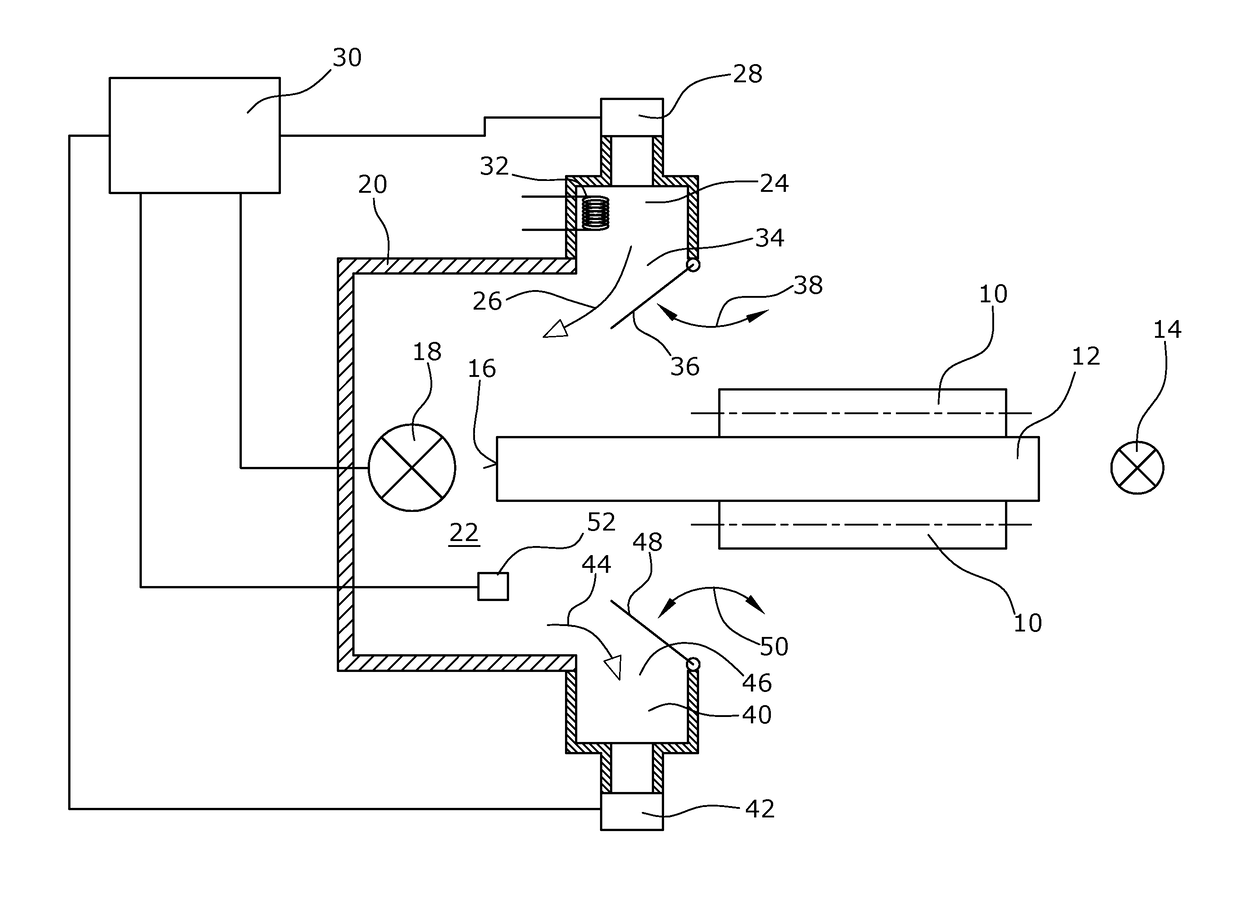
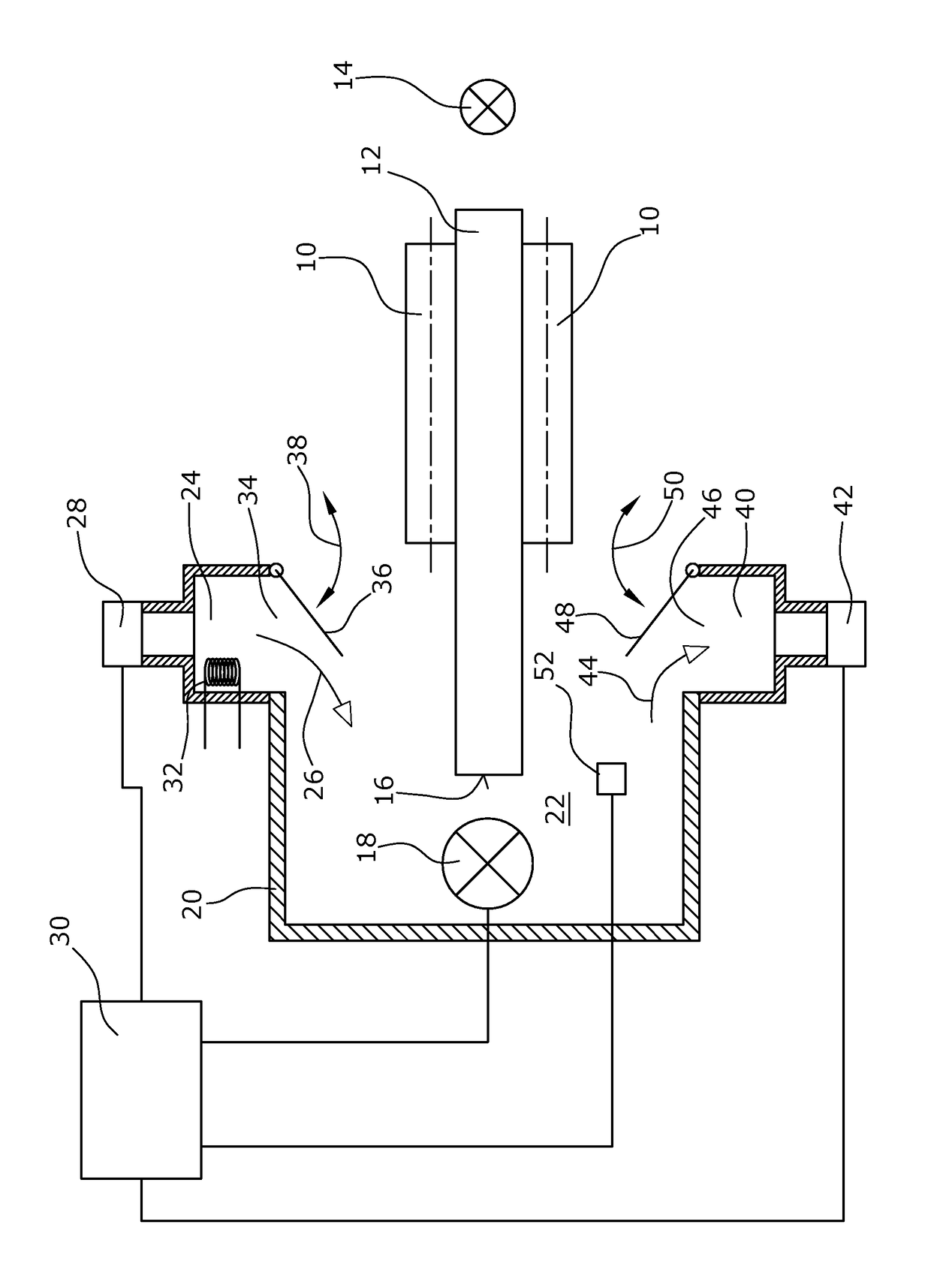
[0029]For drying coated elongated work pieces in a continuous process, a drying device comprises a transport device schematically indicated in the embodiment illustrated by two transport rollers 10. An elongated work piece 12, such as a board for example, is arranged between the two transport rollers 10 and is transported by the transport rollers 10 perpendicularly to the drawing plane in the direction of an arrow 14. In the embodiment illustrated, for example an edge 16 of the workpiece 12 has been coated with lacquer, paint or the like in the coating device arranged upstream of the drying device. For drying, a heat source, in particular one or a plurality of infrared lamps 18, is provided. In the embodiment illustrated these are arranged in parallel with the coated edge or lateral surface 16 of the work piece 12. The heat source 18 is arranged in a housing 20 of the drying device. In the embodiment illustrated, the latter has a U-shaped cross section, with the surface 16 to be dri...


PUM


Abstract

A drying device for drying coated, elongated work pieces in a continuous process including a transport device for transporting the work piece. For drying an edge or surface of the work piece, heat sources are arranged in a drying chamber. In a drying zone, drying vapor is generated during drying. The vapor is removed by an airflow. The airflow is supplied via a supply channel and fans. A controller is provided to control the fans.

Description

CROSS-REFERENCE TO RELATED APPLICATION[0001]This application claims priority to German Patent Application No. 10 2015 205 338.5 filed Mar. 24, 2015, the disclosure of which is hereby incorporated in its entirety by reference.BACKGROUND OF THE INVENTION[0002]Field of the Invention[0003]The present invention relates to a drying device for drying elongated work pieces, in particular work pieces being coated with paint, lacquer or the like, in a continuous process.[0004]Description of Related Art[0005]Elongated work pieces, in particular of wood or plastics, are coated at least in part, for example after profiling. Here, coating is performed in a continuous process in which the work piece is moved through a chamber, for example, in which for example all surfaces, only individual edges etc. are coated in particular with paint, lacquer or the like. Such a device for coating elongated work pieces in a continuous process is described for example in European Application Nos. EP 10 162 699 an...

Claims


Application Information

Patent Timeline
Patent Type & Authority Patents(United States)
IPC IPC(8): F26B21/12F26B15/00F26B3/04F26B15/12F26B3/28F26B3/30
CPCF26B21/12F26B3/04F26B15/12F26B3/30F26B15/00F26B3/283
Inventor STAHL, GERHARD
Owner CEFLA DEUTLAND
Why Eureka
Try Eureka