Charged particle beam writing method, and charged particle beam writing apparatus

a writing method and charge technology, applied in the direction of electrical equipment, electric discharge tubes, basic electric elements, etc., can solve the problems of reducing the accuracy of line width correction, changing resist sensitivity, degrading line width accuracy, etc., and achieving residual error correction in proximity effect correction

Active Publication Date: 2017-12-26
NUFLARE TECH INC
View PDF4 Cites 2 Cited by
  • Summary
  • Abstract
  • Description
  • Claims
  • Application Information

AI Technical Summary

Problems solved by technology

Thus, since the number of shots and the amount of dose increase limitlessly, the pattern writing time also increases limitlessly.
However, if the substrate is irradiated with an increased amount of irradiation energy as higher density electron beams in a short time, another problem occurs in that the substrate overheats resulting in a phenomenon called “resist heating” of changing the resist sensitivity and degrading the line width accuracy.
However, even if the dose has been adjusted by the proximity effect correction operation, if subsequently a temperature correction operation is performed for dose modulation in order to suppress dimensional change (variation) due to the resist heating described above, there arises another problem in that a correction residual error occurs in the proximity effect correction.
In order to cope with this problem, it can be thought to again perform a proximity effect correction calculation, but, it may result in throughput degradation.

Method used


Image

  • Charged particle beam writing method, and charged particle beam writing apparatus
  • Charged particle beam writing method, and charged particle beam writing apparatus
  • Charged particle beam writing method, and charged particle beam writing apparatus

Examples


first embodiment

[0029]A first embodiment of the present invention describes a writing method and apparatus that can execute a proximity effect correction and a resist heating correction without again performing calculation for the proximity effect correction.

[0030]In the first embodiment, there will be described a configuration in which an electron beam is used as an example of a charged particle beam. The charged particle beam is not limited to the electron beam, and other charged particle beam such as an ion beam may also be used. Moreover, a writing apparatus of a variable shaped beam type will be described as an example of a charged particle beam apparatus.

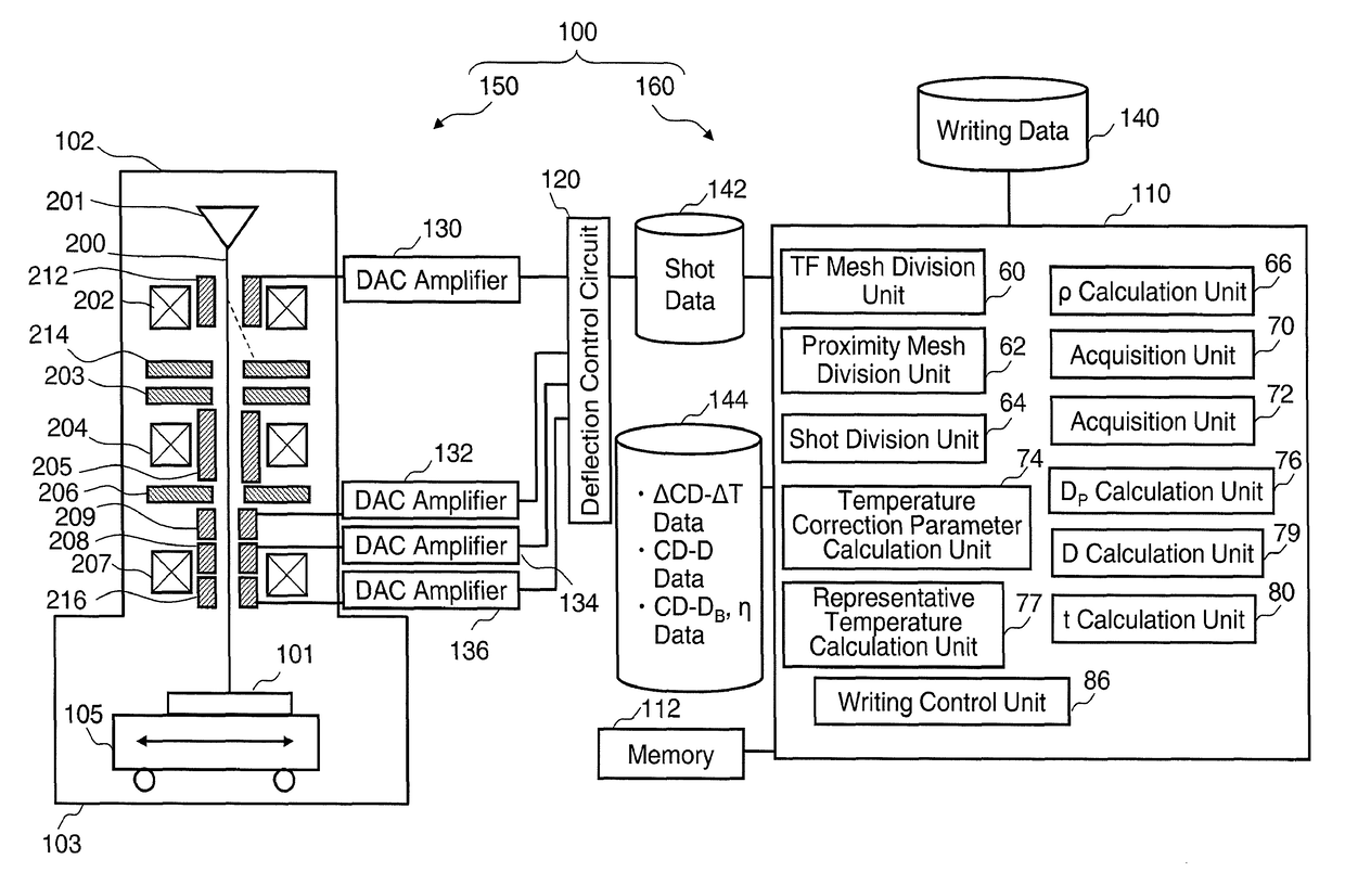
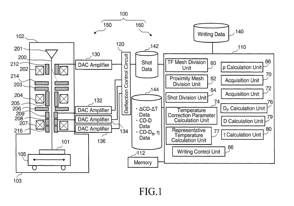
[0031]FIG. 1 is a schematic diagram showing a configuration of a writing apparatus according to the first embodiment. In FIG. 1, a writing apparatus 100 includes a writing mechanism 150 and a control system circuit 160. The writing apparatus 100 is an example of a charged particle beam writing apparatus, and particularly, an example of a vari...


PUM


Abstract

A charged particle beam writing method includes acquiring a pair of a reference dose and a backscatter coefficient for proximity effect correction using a first settling time, acquiring a first relation between a temperature rise amount and a critical dimension variation amount using a second settling time shorter than the first settling time, the backscatter coefficient and the reference dose acquired, calculating a temperature correction parameter depending on a temperature rise amount, for correcting a dose, by using the first relation, and a second relation on a dose and a pattern critical dimension in a case of using the first settling time, calculating a beam irradiation dose by the reference dose and a dose coefficient obtained from the backscatter coefficient of the pair acquired, and the temperature correction parameter, and writing a pattern with a beam based on the dose calculated using the second settling time.

Description

CROSS-REFERENCE TO RELATED APPLICATION[0001]This application is based upon and claims the benefit of priority from the prior Japanese Patent Application No. 2016-062227 filed on Mar. 25, 2016 in Japan, the entire contents of which are incorporated herein by reference.BACKGROUND OF THE INVENTION[0002]Field of the Invention[0003]Embodiments of the present invention relate generally to a charged particle beam writing method, and a charged particle beam writing apparatus, and more specifically relate to a method and an apparatus that perform a proximity effect correction and a resist heating correction, for example.[0004]Description of Related Art[0005]The lithography technique that advances miniaturization of semiconductor devices is extremely important as a unique process whereby patterns are formed in semiconductor manufacturing. In recent years, with high integration of LSI, the line width (critical dimension) required for semiconductor device circuits is decreasing year by year. Fo...

Claims


Application Information

Patent Timeline
Patent Type & Authority Patents(United States)
IPC IPC(8): H01J37/304H01J37/147H01J37/20H01J37/317
CPCH01J37/304H01J37/147H01J37/3174H01J37/20H01J2237/2001H01J37/3026H01J2237/30455H01J2237/30461H01J2237/31769H01J2237/31771
Inventor SUGANUMA, MIZUNANAKAYAMADA, NORIAKI
Owner NUFLARE TECH INC
Why Eureka
Try Eureka