Unlock instant, AI-driven research and patent intelligence for your innovation.

Resonant wireless power receiver circuit and control circuit and wireless power conversion method thereof

a wireless power receiver and control circuit technology, applied in the direction of circuit arrangement, efficient power electronics conversion, inductance, etc., can solve the problems of power loss, inability to function properly, and low or too high rectified output voltage vrect,

Active Publication Date: 2017-12-26
RICHTEK TECH
View PDF9 Cites 2 Cited by
  • Summary
  • Abstract
  • Description
  • Claims
  • Application Information

AI Technical Summary

Benefits of technology

The present invention provides a resonant wireless power receiver circuit that includes a resonant circuit, a switch controlled rectifier circuit, and a feedback control circuit. The resonant circuit includes a receiver coil and a multi-mode switch circuit that operates in a Resonance Short Circuit Operation to limit the level of the AC resonant signal and regulate the rectified output voltage and current. The feedback control circuit controls the multi-mode switch circuit to achieve the desired voltage and current levels. The switch controlled rectifier circuit includes a bridge rectifier circuit and a multi-mode switch circuit that operates in a Synchronous Rectifying Switching Operation, a Resonance Short Circuit Operation, and an OSOC Operation to regulate the rectified output voltage and current. The resonant circuit can also include an impedance matching circuit for better control of the resonant signal. The technical effects of this invention include improved wireless power transfer efficiency and regulation of the output voltage and current levels.

Problems solved by technology

The prior art in FIG. 1 has a drawback that the rectified output voltage VRECT may be too low or too high.
If the off resonance is not corrected or controlled, it could cause power loss, or the received voltage (for example the resonant output voltage VAC and the rectified output voltage VRECT) could be too low such that circuits at the following stage (such as the DC-DC converter 34 and the load 35) cannot function properly.
The prior art in FIG. 2 has the following drawbacks: (A) it requires two output capacitors connected to each other in series, so the equivalent capacitance is half of that of a single capacitor; (B) CR5 has to be a bi-directional control switch; (C) there are only two options for its output voltage, nevertheless as mentioned previously, since the power received by the resonant wireless power receiver circuit with resonance effect is uncertain, the output voltage generated by the prior art rectifier may be too low in 1× mode and too high in 2× mode, i.e., neither 1× nor 2× is proper, which may lead to malfunction or damage of circuits in its following stages.
A drawback of this prior art is that the switch 220 must have an un-preferred relatively high voltage rating for tolerating the energy which is stored in and released from the target resonator.

Method used


Image

  • Resonant wireless power receiver circuit and control circuit and wireless power conversion method thereof
  • Resonant wireless power receiver circuit and control circuit and wireless power conversion method thereof
  • Resonant wireless power receiver circuit and control circuit and wireless power conversion method thereof

Examples


Embodiment Construction

[0041]The drawings as referred to throughout the description of the present invention are for illustration only, to show the interrelations between the circuits and the signal waveforms, but not drawn according to actual scale.

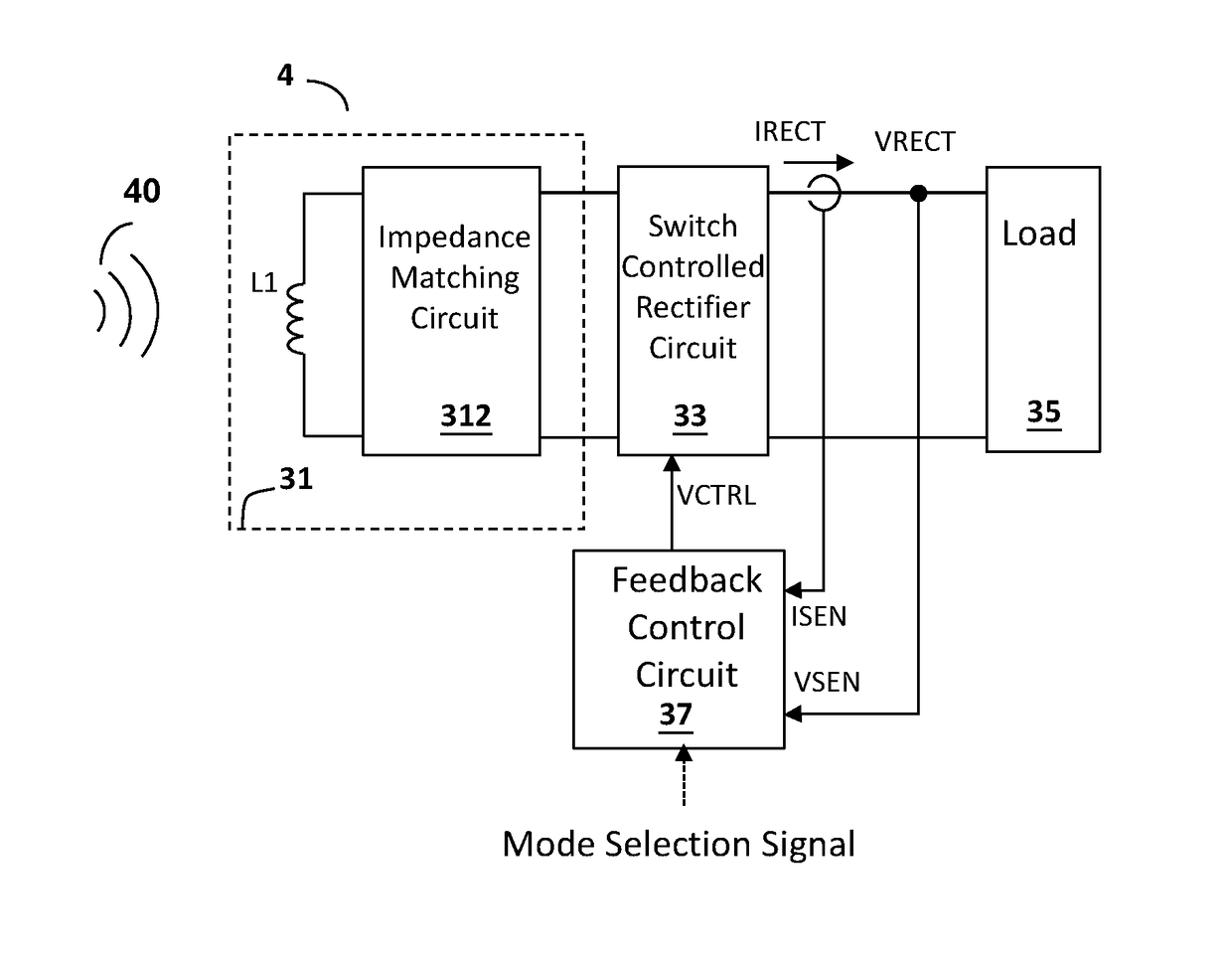
[0042]FIG. 4 shows one embodiment of the resonant wireless power receiver circuit according to the present invention (resonant wireless power receiver circuit 4). The resonant wireless power receiver circuit 4 comprises a resonant circuit 31 which includes a receiver coil L1 and an impedance matching circuit 312, a switch controlled rectifier circuit 33 coupled to the resonant circuit 31, and a load 35 coupled to the switch controlled rectifier circuit 33.

[0043]The wireless power transmission is achieved as thus. In FIG. 4, a resonant wireless power transmitter circuit (not shown) transmits a wireless power 40 to a wireless field (for example but not limited to a magnetic field, an electric field or an electromagnetic field). The wireless power 40 in the wirel...


PUM

PropertyMeasurementUnit
voltage levelaaaaaaaaaa
voltageaaaaaaaaaa
voltageaaaaaaaaaa

Abstract

The present invention provides a resonant wireless power receiver circuit, including: a resonant circuit for receiving a wireless power to generate an AC resonant signal; a switch controlled rectifier circuit which includes a multi-mode switch circuit, for rectifying the AC resonant signal into a rectifier output signal to drive a load, wherein the multi-mode switch circuit includes at least one multi-mode switch; and a feedback control circuit for generating a switch control signal according to a feedback signal related to the rectifier output signal to control the at least one multi-mode switch such that it operates at least in a Resonance Short Circuit Operation to limit the rectifier output signal or to regulate the rectifier output signal. In the Resonance Short Circuit Operation, a positive resonant output node and a negative resonant output node are short-circuited by the multi-mode switch circuit.

Description

CROSS REFERENCE[0001]The present invention claims priority to U.S. 62 / 161,912, filed on May 15, 2015.BACKGROUND OF THE INVENTION[0002]1. Field of Invention[0003]The present invention relates to a resonant wireless power receiver circuit, particularly, to a resonant wireless power receiver circuit with a switching controlled rectifier circuit. The present invention also relates to a control circuit and a resonant wireless power conversion method.[0004]2. Description of Related Art[0005]FIG. 1 shows a prior art resonant wireless power receiver circuit 1. The resonant wireless power receiver circuit 1 comprises a resonant circuit 31, a bridge rectifier circuit 33, a DC-DC conversion circuit 34 and a load 35.[0006]The wireless power transmission is achieved as thus. In FIG. 1, a resonant wireless power transmitter circuit (not shown) transmits a wireless power 40 to a wireless field (for example but not limited to a magnetic field, an electric field or an electromagnetic field). The wir...

Claims


Application Information

Patent Timeline
Patent Type & Authority Patents(United States)
IPC IPC(8): H01F27/42H02J50/12H02M7/217H02M7/219H01F38/00H01F37/00
CPCH02J50/12H02M7/219H02M7/217Y02B70/1441H02J5/005H02M3/04H02M7/04Y02B70/10
Inventor LIU, KUO-CHIWEI, WEI-HSIN
Owner RICHTEK TECH