Rotary screw compressors utilizing viscous damping for vibration reduction

a compressor and viscous technology, applied in the direction of machines/engines, rotary/oscillating piston pump components, liquid fuel engines, etc., can solve the problems of many sources of vibration, reduce the effectiveness of the lubricant as a damping mechanism, reduce the resonant response of the rotor, and increase the effect of the viscous damping effect of the sfds

Active Publication Date: 2018-01-02
JOHNSON CONTROLS TYCO IP HLDG LLP
View PDF12 Cites 0 Cited by
  • Summary
  • Abstract
  • Description
  • Claims
  • Application Information

AI Technical Summary

Benefits of technology

[0013]Another advantage of the present invention is that the lubricant is provided to the SFD either as a cooled lubricant or a pressurized lubricant so that bubbles formed by any gas dissolved in the lubricant are minimized or eliminated. The presence of bubbles in the lubricant can be detrimental, as any forces from the vibrating rotor can form or create bubbles and reduce the effectiveness of the lubricant as a damping mechanism.
[0014]Another advantage of the present invention is that the viscous damping contribution of the SFDs is proportional to the vibrating velocity of the shaft, so that as vibration amplitude of the shaft increases, the effect of the viscous damping by the SFDs also increases. The addition of damping to the spring / mass system of the rotor and its bearings and supports significantly reduces the resonant response of the rotor and reduces any vibration associated with excitation of resonant frequencies in the system. The viscous damping effect of the SFDs assists in damping lateral natural frequencies. Although SFDs may be effective on all screw compressors, they are most effective in damping natural frequencies in large compressors, that is, having rotor diameters 355 mm and larger, in which damping of resonances is difficult by other means.
[0015]A further advantage of SFDs in large screw compressors with anti-friction bearings is a significant improvement in the application range of such compressors in increased operating pressures. In addition, the SFDs used in conjunction with anti-friction bearings provide a damping advantage previously associated only with hydrodynamic bearings, while also providing ease of service and improved tolerance and clearance ranges.
[0016]A further advantage of the application of SFDs in screw compressors is realized in variable speed applications. Many screw compressors are applied today with variable speed drive as a means of capacity control. However, changing the speed over large ranges means that the excitation frequencies of rotational speed, lobe passing, and harmonics of lobe passing will provide potential excitation over a very wide range of speed-dependent frequencies. SFDs reduce the rotor's reaction to this excitation at any frequencies that might be near any critical mode of vibration of the rotor or rotors in multiple rotor compressors so that rotor operation can be more independent of speed. This reduces rotor vibration at those speeds and corresponding frequencies that would otherwise have to be avoided by skipping the speeds and corresponding frequencies of operation at which excessive rotor vibration occurs.
[0017]A further advantage is that SFDs may allow an increase in the maximum discharge pressure of the screw compressor, and / or the input power. For a screw compressor, many other characteristics other than vibration limits control discharge pressure and power, including but not limited to housing maximum operating pressure, bearing life, drive shaft strength and rotor deflection. In cases where vibration becomes the limiting factor, it would be possible for a large compressor, that is a compressor having rotor diameter of 355 mm, the discharge pressure and power output may be increased by up to 100% above levels achievable without damping, without exciting rotor natural frequencies that might occur at the higher pressures without damping. The increase in discharge pressure may depend on other factors and will vary with rotor diameter. Increases in discharge level typically may be in the range of 5-50%, 10-25% or 5-15% depending on those factors.

Problems solved by technology

There are many sources of vibration in a screw compressor.

Method used


Image

  • Rotary screw compressors utilizing viscous damping for vibration reduction
  • Rotary screw compressors utilizing viscous damping for vibration reduction
  • Rotary screw compressors utilizing viscous damping for vibration reduction

Examples


Embodiment Construction

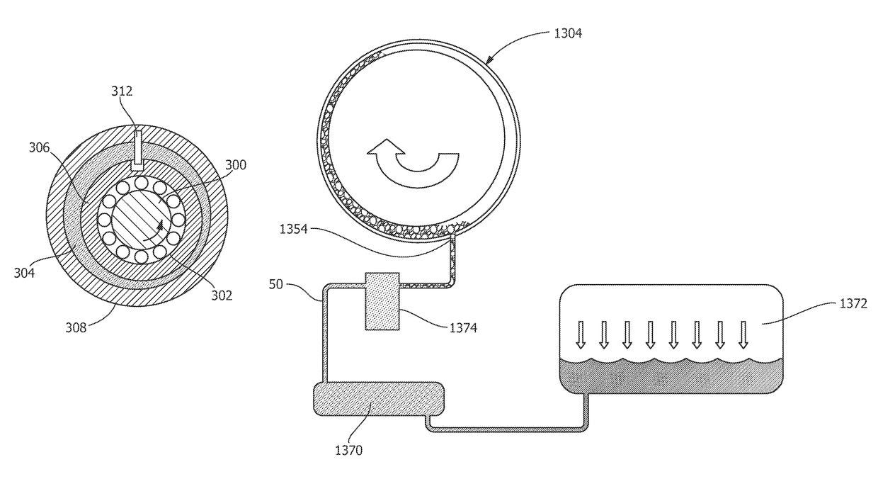
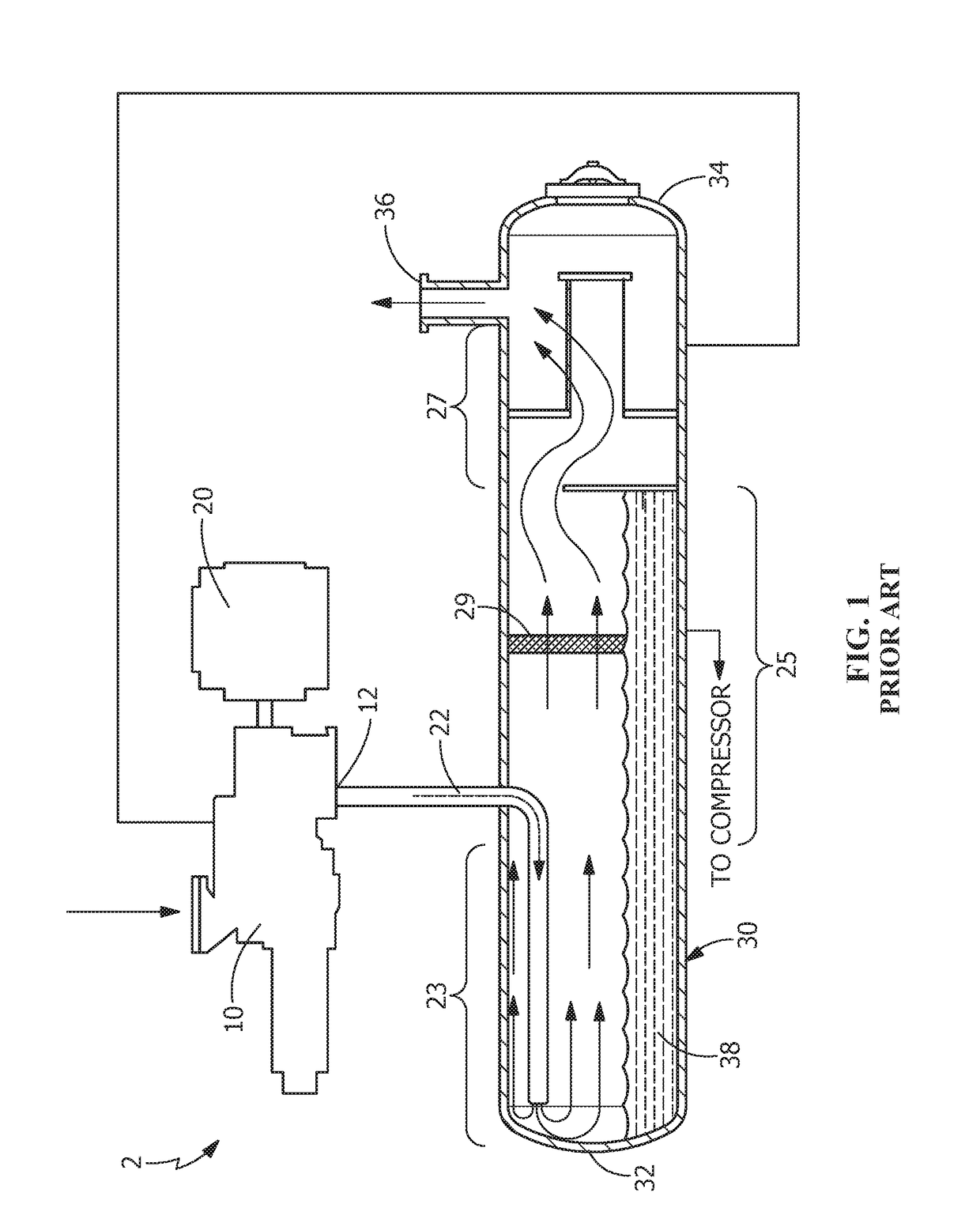
[0039]FIG. 1 depicts a prior art screw compressor assembly 2 shown in cross section. The assembly comprises a screw compressor 10, a motor 20 that drives screw compressor 10 and an oil separator 30. Compressed refrigerant and lubricant from compressor 10 is discharged from the discharge port 12 of screw compressor 10 through conduit 22 into oil separator 30 where compressed refrigerant gas is separated from lubricant, compressed refrigerant gas being discharged through separator discharge port 36 while lubricant 38 is coalesced and allowed to settle for recycling to compressor 10.

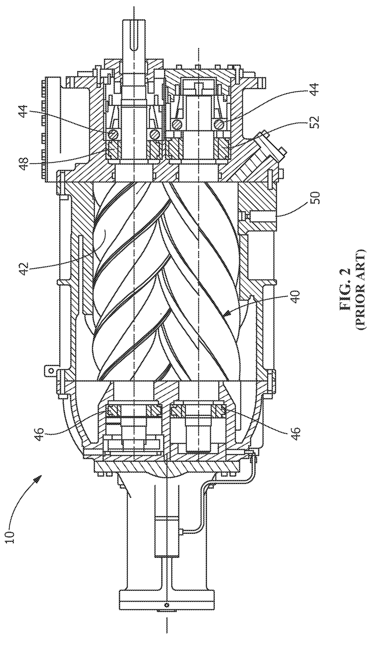
[0040]FIG. 2 is a partial cross section of screw compressor 10 of FIG. 1, depicting a twin screw compressor. While a twin screw compressor is depicted in FIG. 2, one skilled in the art will recognize that screw compressor 10 may also be a single screw compressor or a tri-screw compressor. These compressor designs are subject to vibration, so the vibration damper of the present invention is adaptable to any ...


PUM


Abstract

A screw compressor utilizing radial and axial or thrust bearings to maintain the position of the rotors radially and axially and utilizing a damping fluid to dampen rotor vibrations. The damping fluid may conveniently be provided in the form of lubricant that is already used in the compressor to seal the clearances between the rotors and between the rotors and the cylinder during compression. The damping fluid is included in a squeeze film damper, arranged in a parallel arrangement with the radial or thrust bearings, which provides viscous damping to the rotor. The introduction of additional viscous damping such as may be provided by squeeze film dampers may result in significant reduction of compressor vibration regardless of the source of vibration.

Description

FIELD OF THE INVENTION[0001]The present invention is directed to rotary screw compressors employing bearings and a damping fluid for positioning and damping of the rotating screw, and more specifically, radial and axial bearings for accurate positioning of the rotating screws and a squeeze film damper to provide damping of vibrations in parallel with the anti-friction bearings.BACKGROUND OF THE INVENTION[0002]Rotary screw compressors are used to compress a wide variety of gases. These compressors are used for industrial refrigeration and for air conditioning. They are also used for air compression and for compressing gases such as natural gas. In these circumstances, the screw compressors may be located in remote locations and required to run for long periods of time, weeks or months, with minimal service. These compressors are also used to compress a wide variety of gases for other industrial applications.[0003]Screw compressor may utilize two rotors on parallel axes, referred to a...

Claims


Application Information

Patent Timeline
Patent Type & Authority Patents(United States)
IPC IPC(8): F01C1/16F04C29/00F03C4/00F03C2/00F04C18/28F04C18/16F04C29/02F16C17/02F16C33/10F16C32/06
CPCF04C29/0021F04C18/16F04C18/28F04C29/025F16C33/107F04C2270/12F16C17/026F16C32/0644F16C32/0659F04C2240/54F04C29/0007F16F15/0237
Inventor PILLIS, JOSEPH W.TYCHSEN, HOLGERARMENTROUT, RICHARD W.
Owner JOHNSON CONTROLS TYCO IP HLDG LLP
Why Eureka
Try Eureka