Power conversion device

a power conversion device and power technology, applied in the direction of dc-ac conversion without reversal, efficient power electronics conversion, climate sustainability, etc., can solve the problem of induced switching noise increase, and achieve the effect of suppressing switching nois

Active Publication Date: 2018-01-09
NISSAN MOTOR CO LTD
View PDF14 Cites 0 Cited by
  • Summary
  • Abstract
  • Description
  • Claims
  • Application Information

AI Technical Summary

Benefits of technology

[0005]In view of the problems described above, an object of the present invention is to provide a power conversion device that is capable of reducing the effect of switching noise that is generated when drive circuits drive switching elements.
[0007]In the power conversion device of the present invention, a power supply transformer is provided for each of the power supply circuits, and a predetermined gap is formed between drive circuits without being constrained by the power supply transformer. Accordingly, compared to when the gap between drive circuits is constrained by the power supply transformer, it is possible to spread the gap between drive circuits to thereby suppress switching noise that is induced when driving the switching elements.

Problems solved by technology

Consequently, the interval between the drive circuits on the substrate could only be separated by a distance equivalent to the dimension of the power supply transformer, which led to an increase in switching noise that is induced when switch-driving the semiconductor module.

Method used


Image

  • Power conversion device
  • Power conversion device
  • Power conversion device

Examples


first embodiment

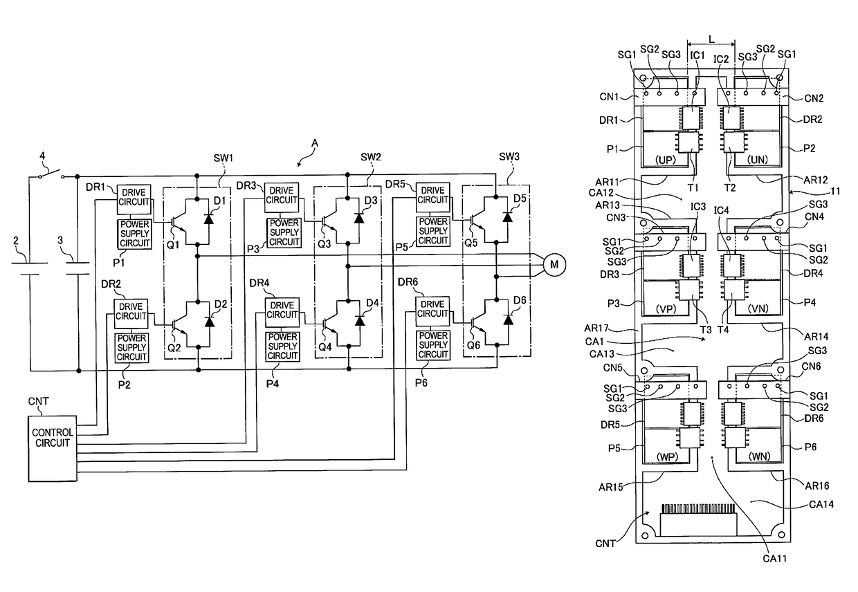
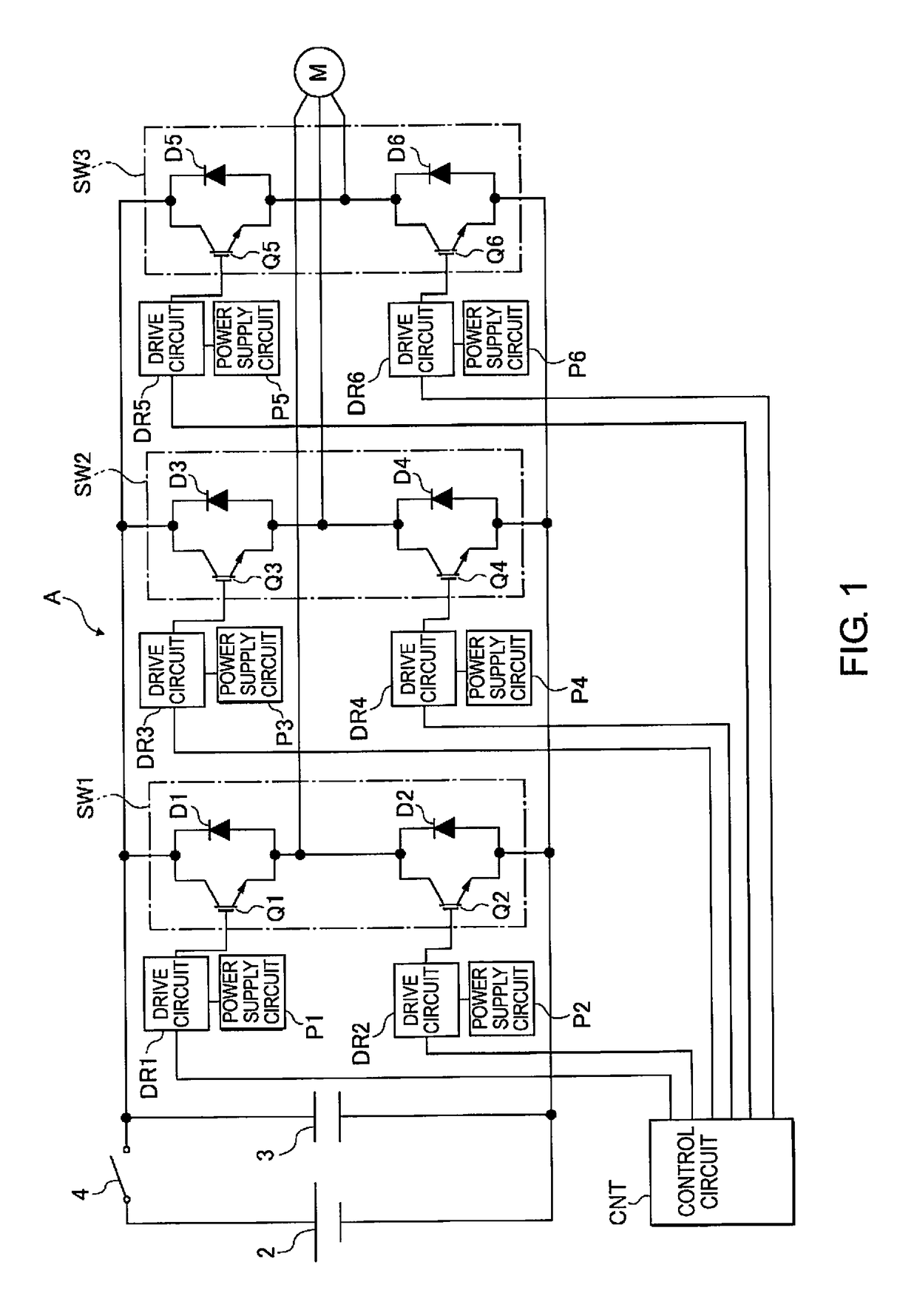
[0019]First, the configuration of the power conversion device of the first embodiment will be described. FIG. 1 is a circuit diagram illustrating the circuit configuration of the power conversion device A of the first embodiment; this power conversion device A converts DC power that is supplied from a DC power source 2 into three-phase AC power and supplies the power to a rotating electrical machine M in order to control the driving of the rotating electrical machine M.

[0020]This power conversion device A comprises switching units SW1, SW2, SW3 as switching means for each of the phases of U-phase, V-phase and W-phase. Each of these well-known switching units SW1, SW2, SW3 comprises upper arm switching elements Q1, Q3, Q5 and lower arm switching elements Q2, Q4, Q6. Then, rectifier cells D1-D6 are respectively provided to switching elements Q1-Q6 in parallel. In addition, the DC power source 2 and a smoothing capacitor 3 as a power storage means are connected to each of the switching...

second embodiment 2

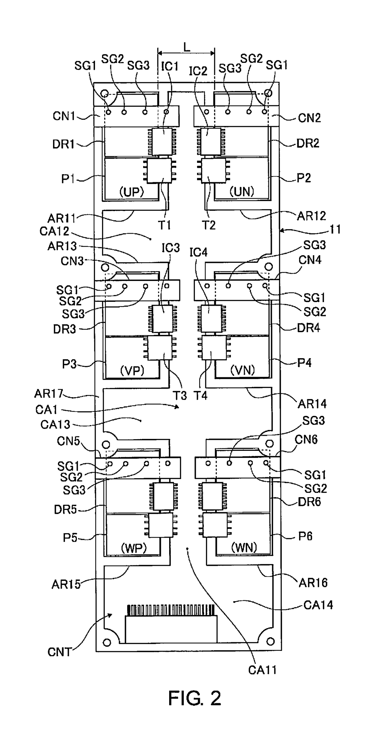
[0056]The power conversion device of the second embodiment illustrates an example in which the arrangements of the switch circuits IC1-IC6 as well as the power supply transformers T1-T6 are changed, and the shapes of the drive-circuit / power supply-circuit arrangement and wiring regions UP, UN, VP, VN, WP, WN are varied, as illustrated in FIG. 5.

[0057]That is, compared with the first embodiment, the lateral dimensions of the drive-circuit / power supply-circuit arrangement and wiring regions UP, UN, VP, VN, WP, WN in FIG. 5 are formed relatively large, and the vertical dimensions are formed relatively small. Moreover, in addition to the foregoing, the width dimension of the longitudinal wiring region CA211 in the control circuit arrangement and wiring region CA201 in the lateral direction of FIG. 5 is narrowed, while the width dimensions of the transverse wiring regions CA212-CA214 in the vertical direction of FIG. 5 are widened. The drive-circuit / power supply-circuit arrangement and w...

third embodiment

[0060]The power conversion device of the third embodiment is an example in which the arrangement of the connection parts CN31-CN36 of the power module 313 is varied from the first embodiment, as illustrated in FIG. 6. Here, accompanying the above, the shapes of the drive-circuit / power supply-circuit arrangement and wiring regions UP, UN, VP, VN, WP, WN as well as the arrangement of the connection parts CN31-CN36, are varied from the first and second embodiments as well, as illustrated in FIG. 7.

[0061]That is, in the power module 313 illustrated in FIG. 6, the connection parts CN31-CN36 are arranged on the outer side upper corners of the switching element mounting regions 121a, 121b, 122a, 122b, 123a, 123b.

[0062]Then, the drive-circuit / power supply-circuit arrangement and wiring regions UP, UN, VP, VN, WP, WN are arranged vertically in the drawing so as to surround the connection parts CN31-CN36, and the outer perimeter thereof is surrounded by the isolating regions AR31-AR36. Addit...


PUM


Abstract

A power conversion device is mounted with a control circuit, a plurality of drive circuits for driving switching elements in response to control signals from the control circuit, and a plurality of power supply circuits for supplying power to the drive circuits on a substrate. The power conversion device has a drive-circuit / power supply-circuit placement and wiring regions of a high current system in which the drive circuits and the power supply circuits are disposed on the substrate are provided for the respective switching elements with isolating regions interposed between the drive-circuit / power supply-circuit placement and wiring regions and the control circuit of a low current system. A gap is formed between the pairs of the drive-circuit / power supply-circuit regions. Power supply transformers are provided for transforming a voltage supplied from the control circuit for the respective power supply circuits in-between the isolating regions.

Description

CROSS-REFERENCE TO RELATED APPLICATIONS[0001]This application is a U.S. National stage application of International Application No. PCT / JP2014 / 081935, filed Dec. 3, 2014.BACKGROUNDField of the Invention[0002]The present invention relates to a power conversion device.Background Information[0003]Conventionally, a power conversion device that aims to reduce the size and inductance is known. for example, as disclosed in Japanese Laid-Open Patent Application No. 2008-118815 (Patent Document 1). This prior art is structured such that a power supply transformer is disposed on a substrate between a semiconductor module as a drive circuit that drives switching elements of an upper arm and a semiconductor module as a drive circuit of a lower arm. Therefore, it becomes possible to shorten the transmission distance of control power between the power supply transformer and the semiconductor modules. It thereby becomes possible to reduce variation in the control power supply voltage that is suppl...

Claims


Application Information

Patent Timeline
Patent Type & Authority Patents(United States)
IPC IPC(8): H02M1/08H02M7/537H02M7/00H02P27/06H02M1/00
CPCH02M1/08H02M7/003H02M7/537H02P27/06H02M2001/0054H02M7/48Y02B70/10H02M1/0054
Inventor KAWAGUCHI, SHINJI
Owner NISSAN MOTOR CO LTD
Why Eureka
Try Eureka