Axial turbomachine blade with platforms having an angular profile

a technology platforms, which is applied in the direction of machines/engines, efficient propulsion technologies, mechanical apparatuses, etc., can solve the problems of reducing performance, and affecting the performance of axial turbomachine blades

Inactive Publication Date: 2018-01-16
TECHSPACE AERO
View PDF8 Cites 3 Cited by
  • Summary
  • Abstract
  • Description
  • Claims
  • Application Information

AI Technical Summary

Benefits of technology

[0051]The present application enables the splitter nose to be de-iced in an optimum manner, especially at its leading edge. Because of this, a larger area of the nose can be de-iced. The heat of the fluid passes though a reduced thickness of material, thereby improving the thermal efficiency of the device. This configuration improves splitter nose de-icing by providing a uniform efficiency on both its two primary and secondary flow separator walls.
[0052]This splitter nose architecture is simple. It allows both weight reduction and savings. Various areas of material can be removed compared with a conventional nose. Also, the manufacturing processes can be simplified.
[0053]The present application employs the turbomachine's oil to recover heat. The heat transfer fluid can flow in ducts with reduced sections and having elbows. Hot air is particularly fluid, allowing it to flow in small sections. Oil has a high thermal capacity, enabling it to work at reduced temperatures in order to match the characteristics of certain materials.

Problems solved by technology

These blocks can change the geometry of the nose and affect the flow of air entering the compressor, which can reduce performance.
As they increase in size the blocks can become particularly heavy.
Thereafter, they may break off and be ingested by the compressor, which could damage the rotor and stator blades.
This ingestion is particularly damaging as it has not first passed through the inlet fan.
However, this solution requires complex machining operations.
It would be difficult to choose another material, say a stronger or lighter one, if the thermal conductivity is low.
This exchanger is, however, complicated to implement.
However, the effectiveness of the pipe is reduced at the leading edge of the splitter nose due to the distance which separates them.
It is less effective in the lower part (or internal), and may allow ice to develop on the outer shell of the stator.

Method used


Image

  • Axial turbomachine blade with platforms having an angular profile
  • Axial turbomachine blade with platforms having an angular profile
  • Axial turbomachine blade with platforms having an angular profile

Examples


first embodiment

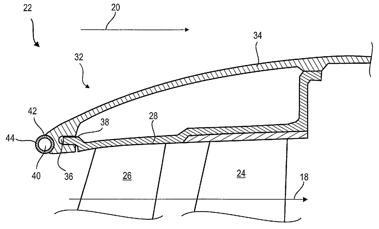
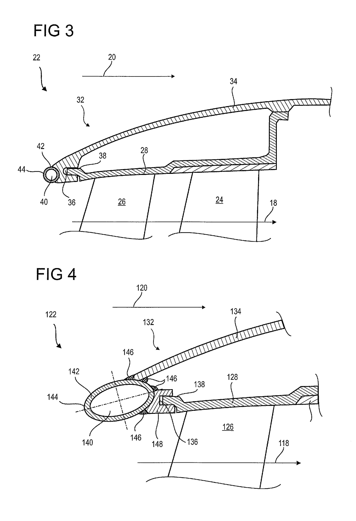
[0059]FIG. 3 illustrates a splitter nose 22 of an axial turbomachine according to the present application.

[0060]The splitter nose 22 is circular in shape. It has a body 32. The latter has a shape of revolution. It comprises an outer wall 34, also of revolution, which is in contact with the secondary flow 20. It is connected to the outer shell 28 of the stator via means of fastening located on its upstream section. Its means of attachment 36 may comprise an annular groove with an axial opening facing downstream. The outer shell 28 may comprise additional means for fixing 38, for example a cylindrical surface designed to mate with the groove 36. The outer shell 28 may also be connected to the outer wall 34 further downstream.

[0061]In order to prevent the formation of ice or to make it melt in a discontinuous manner, the splitter nose 22 has a de-icing device. The latter comprises a channel 40 through which a heat transfer fluid, preferably hot air, circulates. This hot gas can come fr...

second embodiment

[0067]FIG. 4 illustrates a splitter nose according to the present application. FIG. 4 has the same numbering scheme as in previous figures for the same or similar elements, but the numbering is incremented by 100. Specific numbers are used for items specific to this embodiment.

[0068]The splitter nose 122 comprises a body of revolution 132 with an outer wall 134. It has a de-icing device with a channel 140 defined by a wall 142. The channel 140 travels around the splitter nose 122. The cross section of the wall is profiled. The cross section of the wall 142 and the channel 140 are circular. It may have a flattened portion so as to form a cam shape or an ellipse. The upstream end of major axis of the ellipse or of the cam is inclined inwards. This feature allows the flow to be separated more accurately.

[0069]The wall may have a variable thickness, it can be thinner where it is in contact with the flow, and thicker when in contact with the remainder of the nose This design enables the ...

third embodiment

[0072]FIG. 5 illustrates a splitter nose according to the present application. FIG. 5 has the same numbering scheme as in previous figures for the same or similar elements, but the numbering is incremented by 200. Specific numbers are used for items specific to this embodiment.

[0073]The splitter nose 222 comprises a body of revolution 232 with an outer wall 234. It has a de-icing device with a channel 240 defined by a contoured wall 242. The wall 242 may be welded using weld beads 246 sealing the channel 240. The profile of the wall can comprise curved and straight parts, which facilitates constructing any desired geometry. These straight sections improve the overall strength and the curved parts can concentrate the absorption of impact energy by deforming.

[0074]The profile of the wall can be closed or advantageously open. The body 232 has a front surface 250 extending generally radially. It contributes to delimiting the channel 240 in combination with the wall 242. This feature sav...


PUM


Abstract

The present application relates to a splitter nose of an axial turbomachine designed to separate an annular flow into the turbomachine into a primary flow and a secondary flow for undergoing a thermodynamic cycle. The nose includes a de-icing device with a wall defining, at least partially, an annular channel. A hot oil stream created by the turbomachine circulates in this latter. The oil runs through the circular nose and de-ices it while itself getting cooled. The wall is located so as to form the leading edge of the said splitter nose. The wall is an open or closed strip such as a tube which can be fixed by bonding, welding or recessing. The present application also relates to a multi-flow turbomachine with splitter noses fitted with de-icing devices.

Description

[0001]This application claims priority under 35 U.S.C. §119 to European Patent Application No. 12195999.3, filed 7 Dec. 2012, which is incorporated herein by reference for all purposes.BACKGROUND[0002]1. Field of the Application[0003]The present application relates to dual-flow axial turbomachines. More specifically, the present application relates to the splitter nose of a dual-flow axial turbomachine, the nose splitting the incoming airflow into a primary and a secondary flow. More precisely, the present application relates to de-icing the splitter nose.[0004]2. Description of Related Art[0005]In order to optimise their thrust jet engines have several annular airflows. A primary flow passes through a compressor and a combustion chamber and is then expanded in a turbine. A secondary flow bypasses the compressor, the combustion chamber and the turbine, and then rejoins the main flow at the outlet of the jet engine. The flows are separated by a splitter nose located upstream of the c...

Claims


Application Information

Patent Timeline
Patent Type & Authority Patents(United States)
IPC IPC(8): F01D25/02F02C7/047F01D25/14
CPCF01D25/14F02C7/047F01D25/02Y02T50/672Y02T50/60
Inventor THISE, FREDERICK
Owner TECHSPACE AERO
Why Eureka
Try Eureka