
Coolant circuit for an internal combustion engine and method of operating a coolant circuit

a technology of internal combustion engine and cooling circuit, which is applied in the direction of engine cooling apparatus, control devices of cooling apparatus, machines/engines, etc., can solve the problems of fuel quality not being readily useful as a control variable for controlling a cooling system, premature opening of the valve, and efficiency loss acceptan

Inactive Publication Date: 2018-02-27
AUDI AG
View PDF16 Cites 0 Cited by
  • Summary
  • Abstract
  • Description
  • Claims
  • Application Information

AI Technical Summary

Benefits of technology

The present invention provides a coolant circuit and method for an internal combustion engine that optimized cooling efficiency during a cold start. This is achieved by controlling the opening of a valve based on the mass flow of exhaust gas to prevent rapid heating of the engine and achieve low friction work. The control device determines the injection amount per unit of time to accurately determine the injection amount. The valve can be integrated into a coolant pump or formed by a switchable coolant pump to save components and installation space.

Problems solved by technology

This oftentimes leads to premature opening of the valve, when the coolant temperatures are too low so that efficiency losses have to be accepted.
However, the fuel quality is not readily useful as a control variable for controlling a cooling system because of the absence of a stoichiometric conversion of the fuel, in particular during a cold start of the internal combustion engine.

Method used


Image

  • Coolant circuit for an internal combustion engine and method of operating a coolant circuit
  • Coolant circuit for an internal combustion engine and method of operating a coolant circuit

Examples


Embodiment Construction

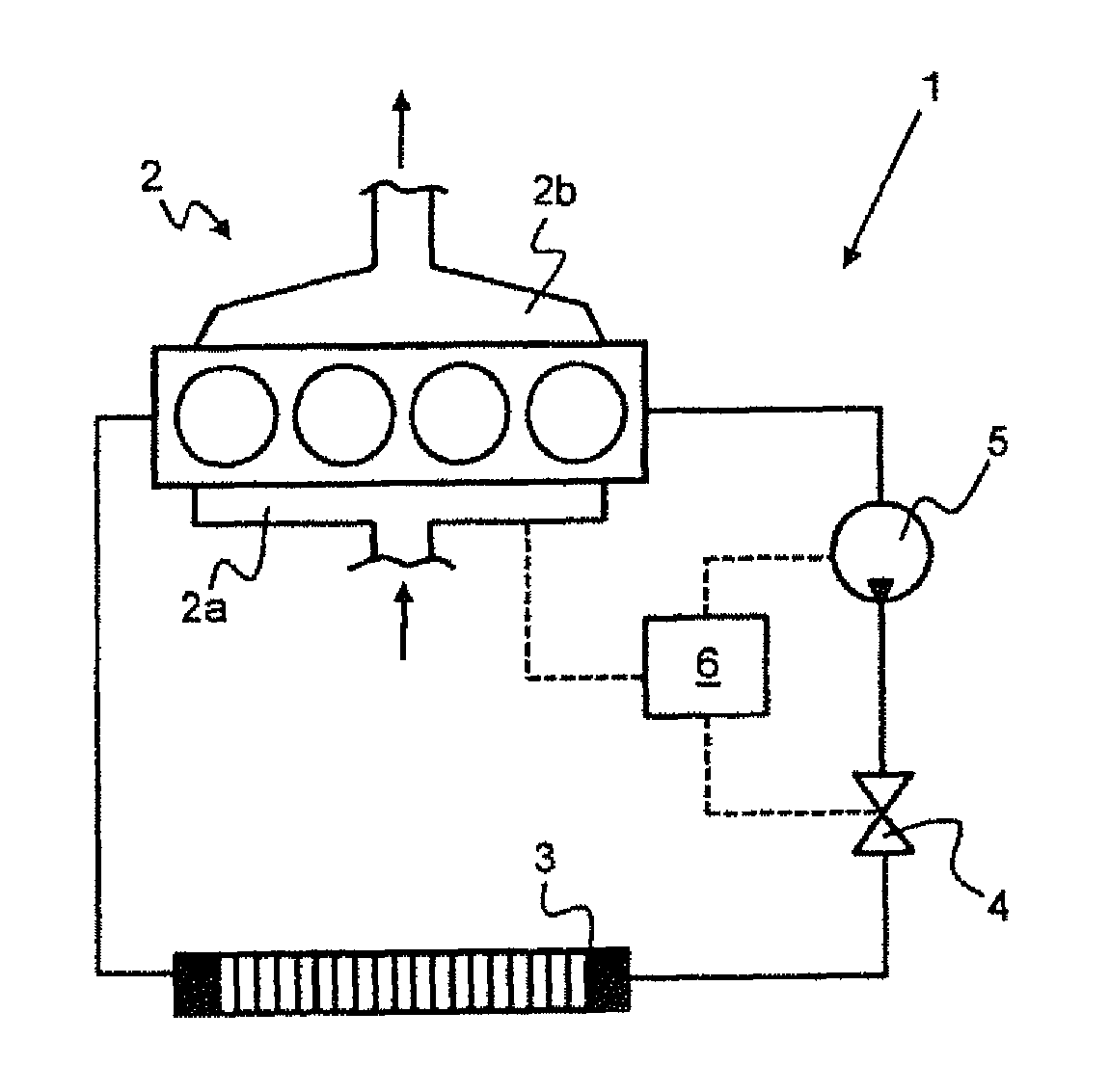
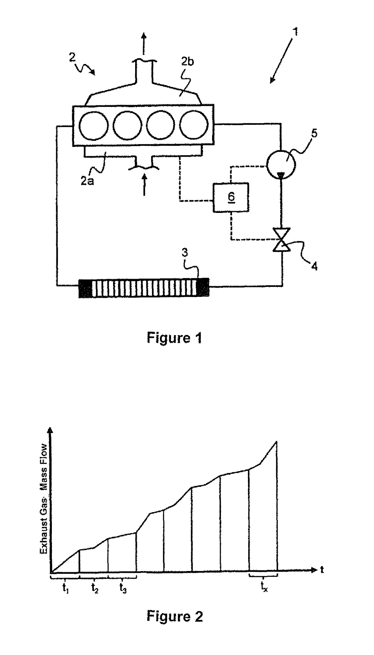
[0021]According to FIG. 1, a coolant circuit 1 for an internal combustion engine 2 has a heat sink 3. The heat sink 3 is circulated by ambient air on one hand, and coolant on the other hand. As a result of the realized heat exchange, coolant circulating in the coolant circuit 1 cools down. The coolant circulation is implemented by a coolant pump 5, with a switchable valve 4 being able to stop the coolant circulation. The internal combustion engine 2 has multiple combustion chambers 2c in which fuel is combusted so that the internal combustion engine 2 is heated. The generated heat can be dissipated by the coolant to the heat sink 3. The fuel is injected either into the intake system 2a or directly into the combustion chambers 2c and then mixed with intake air. Spent fuel-air mixture is expelled through the exhaust system 2b. A control device 6 ascertains the amount of injection of fuel per unit of time and determines the exhaust gas mass flow through the exhaust system 2b. The contr...


PUM


Abstract

The invention relates to a coolant circuit (1) for an internal combustion engine (2), wherein the coolant can circulate between the internal combustion engine (2) and a heat sink (3) depending upon a switchable valve (4), which is closed in the initial state during a cold start of the internal combustion engine (2), wherein the valve (4) can be switched to an at least partially opened sequential state depending on an exhaust gas mass flow emitted by the internal combustion engine (2), and wherein a control device (6) determines an integral of the exhaust gas mass flow with respect to the time and switches the valve (4) into the sequential state when an integral threshold value is exceeded.

Description

CROSS-REFERENCES TO RELATED APPLICATIONS[0001]This application is the U.S. National Stage of International Application No. PCT / EP2012 / 002784, filed Jun. 30, 2012, which designated the United States and has been published as International Publication No. WO 2013 / 017188 and which claims the priority of German Patent Application, Serial No. 10 2011 108 953.9, filed Jul. 29, 2011, pursuant to 35 U.S.C. 119(a)-(d).BACKGROUND OF THE INVENTION[0002]The invention relates to a coolant circuit for an internal combustion engine, wherein the coolant can circulate between the internal combustion engine and a heat sink as a function of a switchable valve which is closed in the initial state during a cold start of the internal combustion engine, and to a method of operating a coolant circuit.[0003]Such coolant circuits are used in particular in the automotive industry to cool coolant, heated by the internal combustion engine, through circulation via the heat sink. In this way, the internal combust...

Claims


Application Information

Patent Timeline
IPC IPC(8): F01P7/14F01P7/16
CPCF01P7/14F01P7/162F01P2037/02F01P2007/146
Inventor GRAF, JOHANN
Owner AUDI AG
Learn More