Control system and method

a control system and control method technology, applied in the direction of gearing control, electric energy vehicles, road vehicle drive control systems, etc., can solve the problems of affecting the operation of the system

Active Publication Date: 2018-03-20
JAGUAR LAND ROVER LTD
View PDF19 Cites 2 Cited by
  • Summary
  • Abstract
  • Description
  • Claims
  • Application Information

AI Technical Summary

Benefits of technology

[0008]a controller configured, in dependence on said monitoring means determining that said one or more operating parameters are above a predefined operating threshold or outside a predefined operating range, to output: (a) a notification to the user to select said low range; and / or (b) a transfer case control signal to the transfer case automatically to select said low range. By monitoring said one or more operating parameters, the control system can operate the transfer case automatically to select said low range. Alternatively, the control system can output a notification to the user to indicate that the low range of the transfer case should be selected. At least in certain embodiments, the control system can operate to prevent or reduce damage to the powertrain. In particular, the control system can operate to protect the launch control clutch and / or the transmission lubricating fluid from heat damage.
[0034]According to a yet further aspect of the present invention there is provided a control system for a vehicle powertrain, the control system being configured to output a variable brake control signal for providing haptic feedback. The variable brake control signal can induce a perceptible vehicle movement, for example a vibration (or ‘shudder’) which is transmitted into the vehicle cabin to provide the driver with haptic feedback. The variable brake control signal could induce a perceptible fluctuation in the vehicle speed or acceleration. The variable brake control signal could, for example, be supplied to an anti-lock brake system (ABS) modulator to cause a light intermittent application of the brakes. The control system can thereby operate the vehicle brake system to provide haptic feedback to the driver.

Problems solved by technology

The relative movement of the friction plates generates considerable heat which can potentially damage the clutch and, in the case of wet clutches immersed in a lubricating fluid, may result in degradation of the lubricating fluid.
The problem of heat generation is particularly significant at low vehicle speed (for example <15 kph) when high torque is required.
These techniques rely on inhibiting functionality and this may be undesirable in certain driving scenarios, for example when towing heavy loads.

Method used


Image

  • Control system and method
  • Control system and method
  • Control system and method

Examples


Embodiment Construction

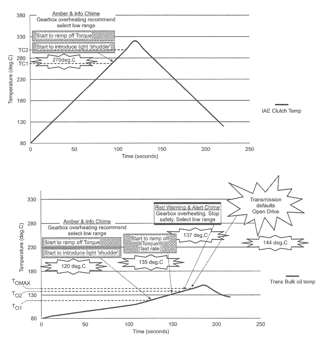
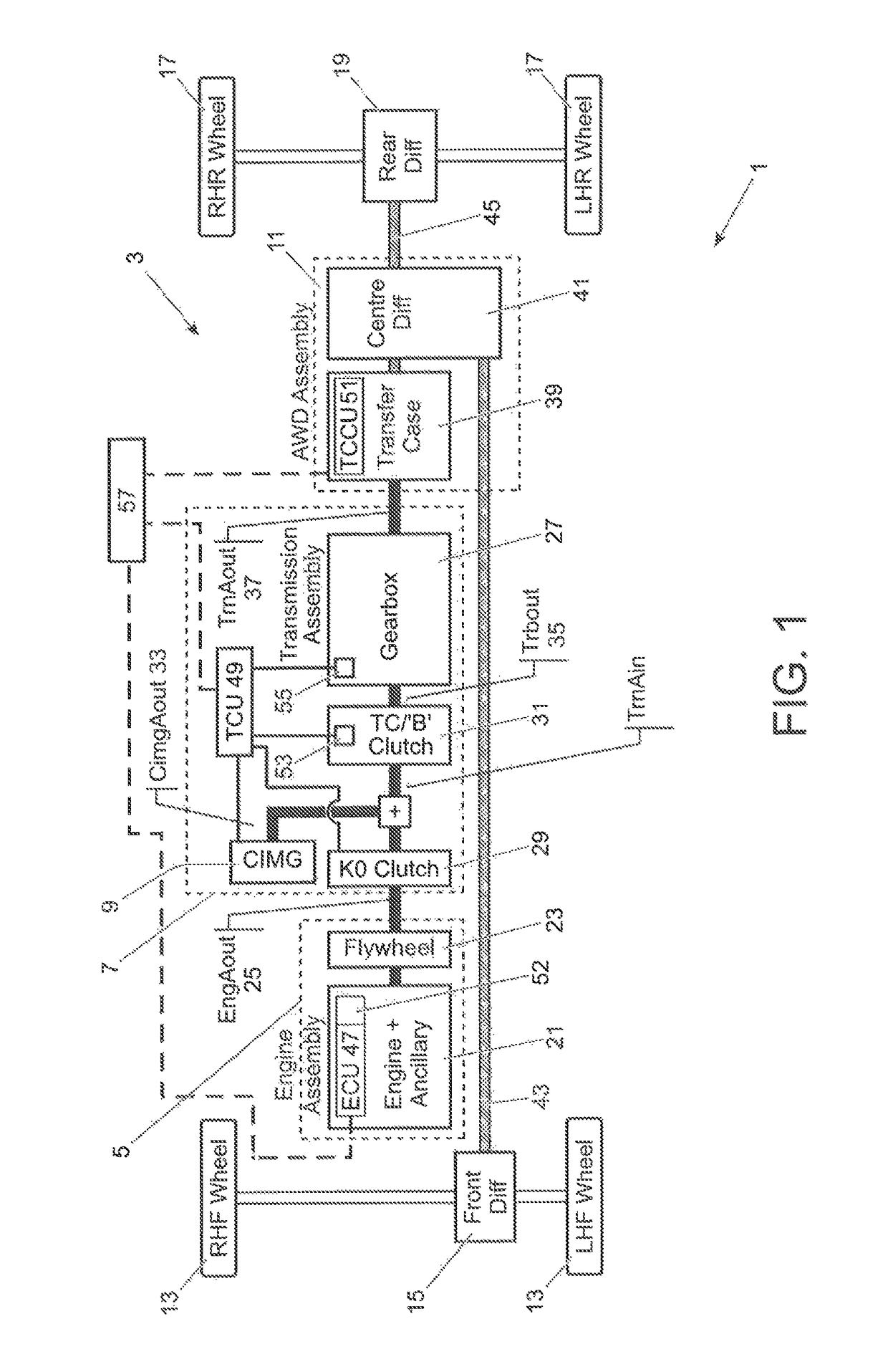
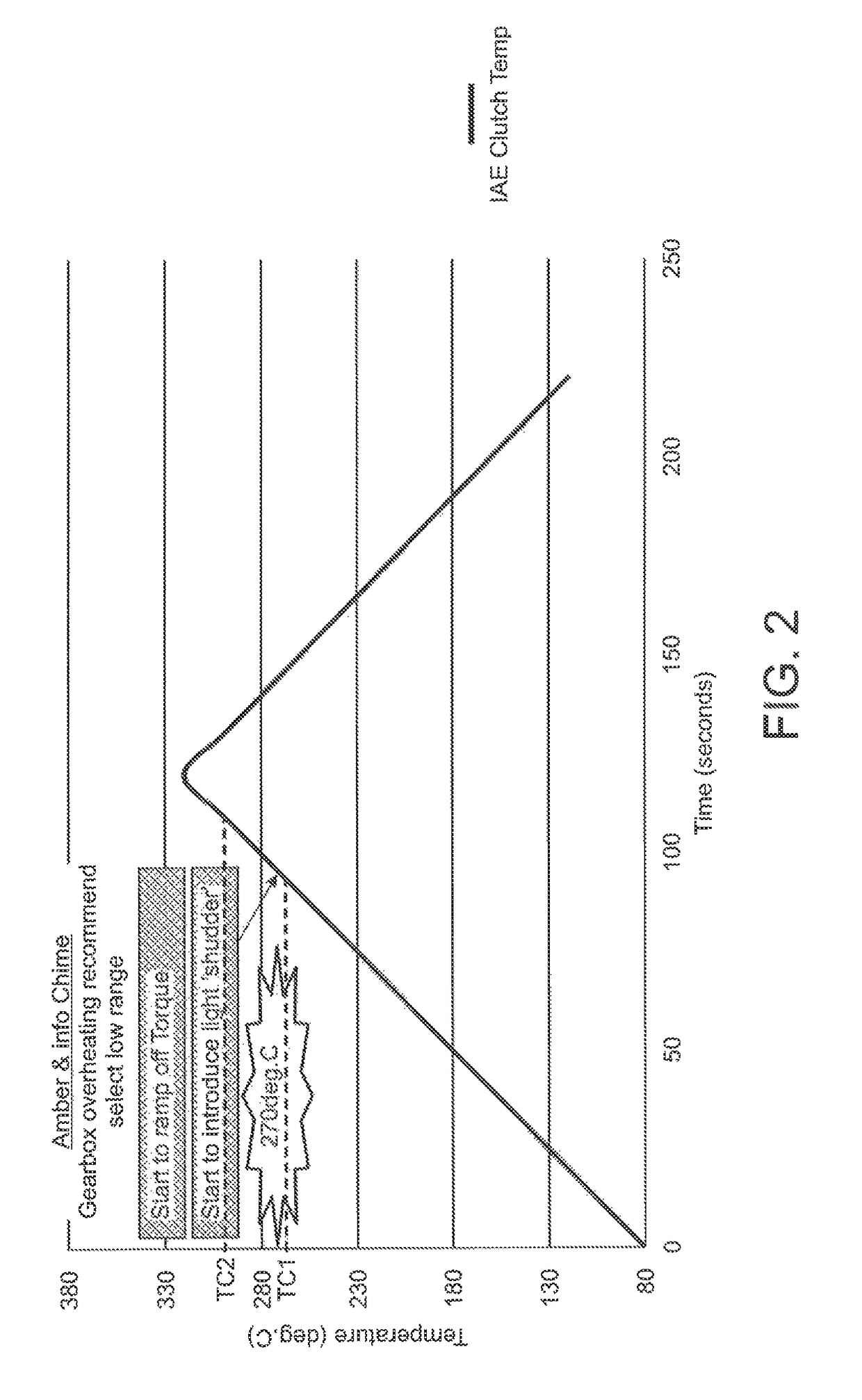
[0044]A vehicle 1 comprising a powertrain 3 in accordance with an embodiment of the present invention will now be described with reference to FIG. 1. The vehicle 1 is a hybrid vehicle comprising an internal combustion engine assembly 5; a transmission assembly 7 having an integrated electric traction motor 9; and an all-wheel drive (AWD) assembly 11. The vehicle 1 is four-wheel drive, the front wheels 13 are driven via a front differential 15 and the rear wheels 17 are driven via a rear differential 19.

[0045]The internal combustion engine assembly 5 comprises an internal combustion engine 21 having a flywheel 23 mounted to an engine output shaft 25. The transmission assembly 7 comprises an automatic transmission 27 coupled to the engine output shaft 25 by a first (K0) clutch 29 and a second (‘B’) clutch 31, both of which are ‘wet’ clutches (i.e. the friction plates are immersed in a lubricating fluid, such as oil). The integrated electric traction motor 9 is disposed inside a transm...


PUM


Abstract

The present invention relates to a control system for a vehicle powertrain (3). The vehicle powertrain (3) includes a transmission (27), a launch control clutch (31), and a transfer case (39) selectively operable in a high range and a low range. The control system includes a monitor (53, 55) for monitoring one or more operating parameters of the launch control clutch (31) and / or the transmission (27). The control system comprises a controller (49) configured, in dependence on said monitoring means determining that said one or more operating parameters are above a predefined operating threshold or outside a predefined operating range, to output a notification to the user to select said low range; and / or to output a transfer case control signal to the transfer case (39) automatically to select said low range.

Description

TECHNICAL FIELD[0001]The present invention relates to a control system and method and particularly, but not exclusively, to a control system and method for a vehicle powertrain. Aspects of the invention relate to a system, to a method and to a vehicle.BACKGROUND OF THE INVENTION[0002]It is known to provide a launch control clutch for selectively coupling an output shaft of an internal combustion engine to an input shaft of a vehicle transmission. The clutch comprises friction plates which are brought into contact with each other when the clutch is engaged to drivingly couple the shafts. To accommodate the speed differential between the input and output shafts, the friction plates are allowed to slip in relation to each other, thereby allowing the speed of the shafts to be matched progressively. The relative movement of the friction plates generates considerable heat which can potentially damage the clutch and, in the case of wet clutches immersed in a lubricating fluid, may result i...

Claims


Application Information

Patent Timeline
Patent Type & Authority Patents(United States)
IPC IPC(8): B60W30/186B60W10/10B60W10/02B60W30/184B60W30/18B60W10/06B60W10/184B60W10/119B60W50/16B60W50/14B60K6/48B60K17/346B60K23/08F16H59/72F16H63/42
CPCB60W30/186B60W10/02B60W10/06B60W10/10B60W10/119B60W30/18027B60W30/1843B60W50/14B60W50/16F16H2059/725F16H59/72F16H2300/18F16H2312/02Y02T10/6221Y02T10/6252Y02T10/6265B60K6/48B60K17/3467B60K23/08B60K2006/4825B60W10/184B60W2420/00B60W2510/0291B60W2510/107B60W2710/0666B60W2710/1005B60W2710/182B60Y2300/186B60Y2300/18025F16H2063/426Y02T10/62B60K23/0808B60W20/30B60W30/184
Inventor PERCY, CRAIG
Owner JAGUAR LAND ROVER LTD
Why Eureka
Try Eureka