Power skiving method having multiple cut strategy

a power skiving and multiple cutting technology, applied in the direction of electric programme control, program control, instruments, etc., can solve the problems of skiving not being performed, difficulty in achieving the effect of equal chip removal thickness and effective chip removal thickness

Active Publication Date: 2018-03-27
KLINGELNBERG AG
View PDF7 Cites 0 Cited by
  • Summary
  • Abstract
  • Description
  • Claims
  • Application Information

AI Technical Summary

Benefits of technology

[0114]The positive effect of the invention is illustrated on the basis of specific numeric examples hereafter.
[0115]Instead of an unfavorable effective rake angle of −20.5° in the first cut of a conventional power skiving method (see FIG. 6A), the most unfavorable rake angle in the first cut of the power skiving method according to certain embodiments (see FIG. 7A) is −16.3°. Such negative effective rake angles primarily occur in the transition region of the tooth flanks 53.v and 54.v to the tooth base 55.v. The effective rake angle in the first cut, for example, was able to be improved from 1.1° to 4.4° on the incoming tooth flank 54.v.
[0116]Furthermore, it can be seen that the trough 115 becomes larger due to the enlargement of the intersection angle of axes, which has a positive effect on the head rake angle for the first cut.
[0117]The effective chip removal thicknesses at equal feed of the tool 100 in relation to the workpiece 50 are also decreased. Accordingly, a higher feed can be used with equal chip removal thickness.
[0118]The method according to certain embodiments comprises at least the following steps, wherein the steps do not necessarily have to be executed in the specified sequence: providing the workpiece 50, providing the power skiving tool 100, which has multiple cutting teeth 111, specifying a first effective intersection angle of axes Σeff1 of the power skiving tool 100 in relation to the workpiece 50, executing a first power skiving machining of the workpiece 50, wherein during the first power skiving machining, the power skiving tool 100 penetrates up to a first infeed depth (for example, 33.33% of the final depth) into the workpiece 50 and the flanks 53.v, 54.v of the periodic structure of the workpiece 50 are pre-machined (this step is shown as an example in FIG. 3A), specifying a second effective intersection angle of axes Σeff2 of the power skiving tool 100 in relation to the workpiece 50, executing a second power skiving machining of the workpiece 50, wherein during the second power skiving machining, the power skiving tool 100 penetrates up to a final infeed depth into the workpiece 50 and the flanks 53.f, 54.f, 55.f of the periodic structure of the workpiece 50 are further machined. This step is shown as an example in FIG. 3C. In the exemplary method, the first effective intersection angle of axes Σeff1 and the second effective intersection angle of axes Σeff2 differ, i.e. Σeff1≠Σeff2.
[0119]The plunging of the tool 100, or the cutting teeth 111 of the tool 50, into the material of the workpiece 50 is specified, for example, by the axial distance a of the axes R1 and R2. The axial distance for a first cut and for a second (final) cut can therefore be assumed to be given according to one embodiment. According to certain embodiments, a first effective intersection angle of axes Σeff1 and a second effective intersection angle of axes Σeff2 can be ascertained by computer, for example. In the scope of this ascertainment, the first pitch circle diameter for the first power skiving machining (i.e., for the first cut) and the second pitch circle diameter for the second power skiving machining (i.e., for the second cut) are set equal. Because the axial distance a1 for the first power skiving machining and the axial distance a2 for the second power skiving machining are known, the first effective intersection angle of axes Σeff1 and the second effective intersection angle of axes can can now be ascertained by computer.

Problems solved by technology

If inclined power skiving tools are used, in the extreme case, skiving cannot be performed without collision using an optimum power skiving tool for the final cut at a machining depth of approximately 25%.
These differences of the chip forming conditions at the various cutting depths not only result in wear of different levels on the power skiving tool, but rather they can also have an influence on the quality of the generated tooth flanks.
This method property of power skiving can also be problematic in the case of a multiple cut strategy.

Method used


Image

  • Power skiving method having multiple cut strategy
  • Power skiving method having multiple cut strategy
  • Power skiving method having multiple cut strategy

Examples


Embodiment Construction

[0064]Terms are used in conjunction with the present description which are also used in relevant publications and patents. However, it is to be noted that the use of these terms is only to serve for better comprehension. The concept of the invention and the scope of protection of the patent claims are not to be restricted in the interpretation by the specific selection of the terms. The invention may be readily transferred to other term systems and / or technical fields. The terms are to be applied accordingly in other technical fields.

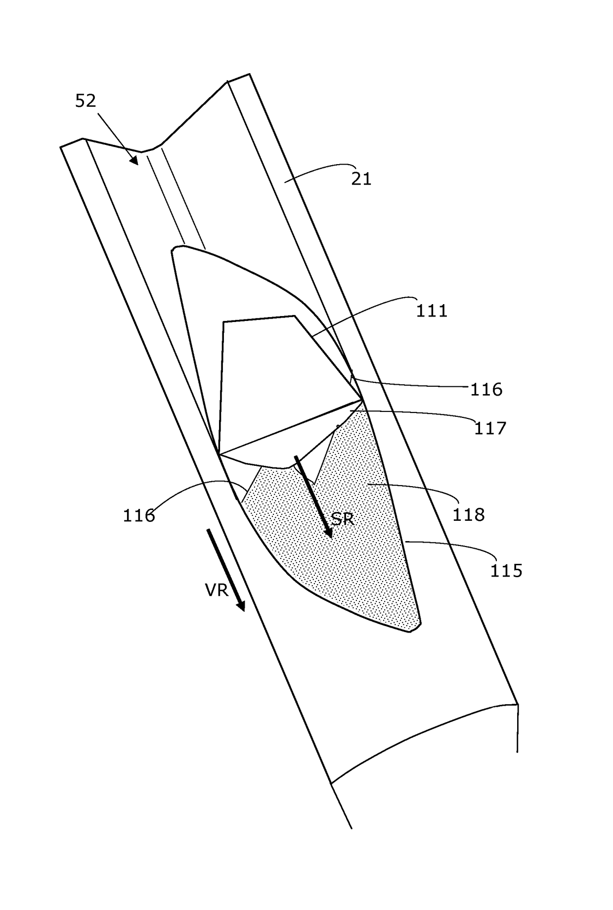
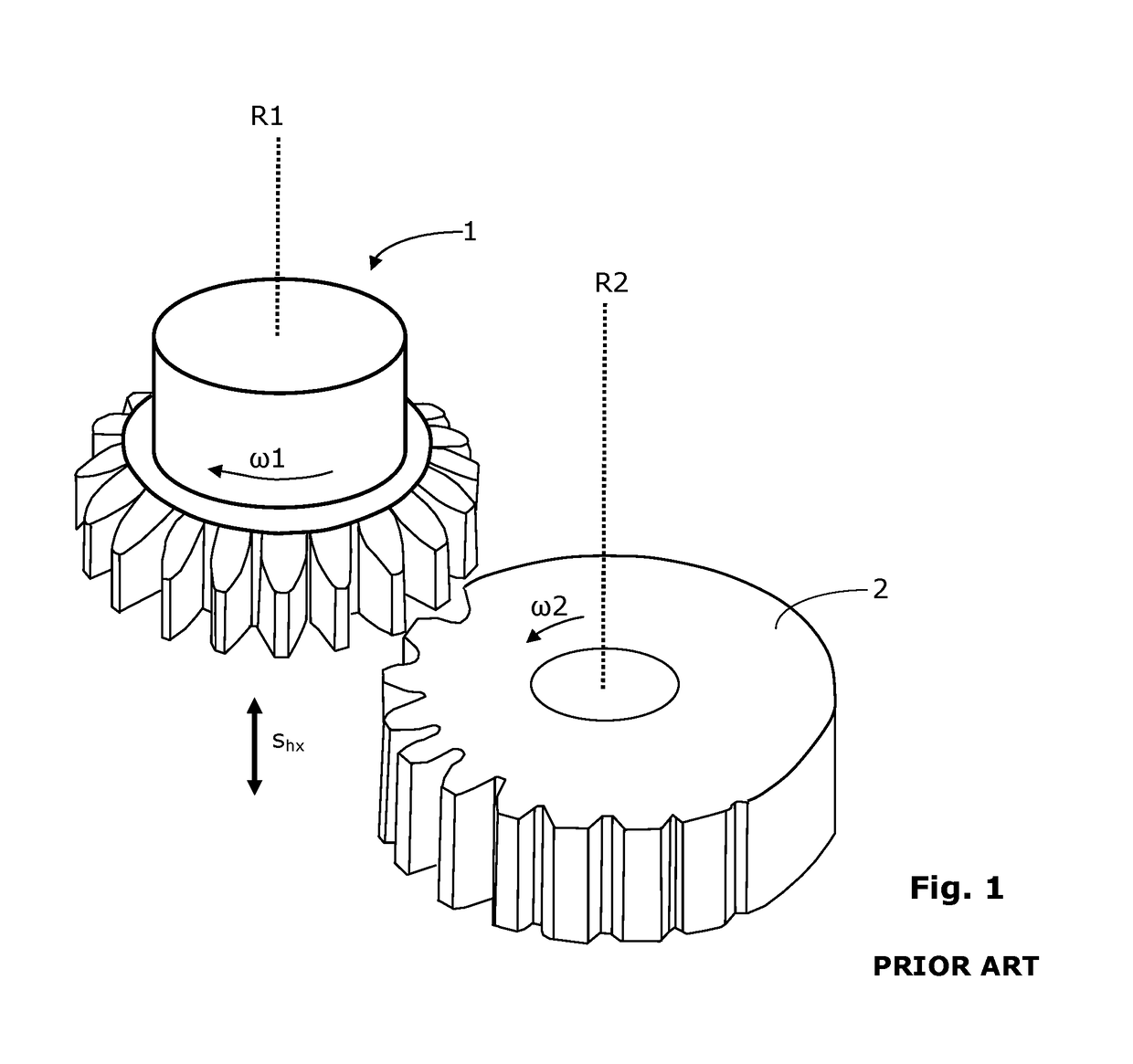
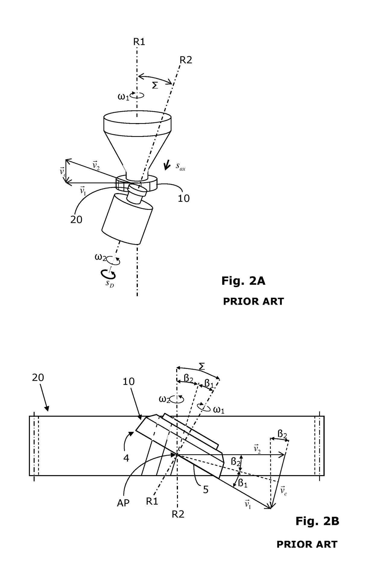
[0065]Rotationally-symmetrical, periodic structures are, for example, gearwheels (such as spur gears) having internal or external gear teeth. However, this can also relate, for example, to brake disks, clutch or transmission elements, and the like. In particular, this relates to the production of pinion shafts, worms, elements for gearwheel pumps, ring joint hubs (ring joints are used, for example, in the automotive sector, to transmit the force from a ...


PUM

PropertyMeasurementUnit
angleaaaaaaaaaa
intersection angleaaaaaaaaaa
rake angleaaaaaaaaaa

Abstract

Method for power skiving a workpiece (50) having a workpiece axis of rotation (R2) and having a rotationally-symmetrical, periodic structure using a power skiving tool (100).

Description

CROSS-REFERENCE TO RELATED APPLICATION[0001]This application claims priority under 35 U.S.C. § 119(a)-(d) to European application no. EP 14198168.8 filed Dec. 16, 2014, which is hereby expressly incorporated by reference as part of the present disclosure.FIELD OF THE INVENTION[0002]The subject matter of the invention is a method for power skiving gear teeth.BACKGROUND OF THE INVENTION[0003]There are numerous methods for manufacturing gearwheels. In the case of cutting soft pre-machining, a differentiation is made between hobbing, gear shaping, generating planing, and power skiving. Hobbing and power skiving are so-called continuous methods.[0004]The gear shaping method can be described or illustrated by a cylinder wheel gearing, since the intersection angle (also called the intersection angle of axes) between the axis of rotation R1 of the shaping tool 1 and the axis of rotation R2 of the workpiece 2 is 0°, as schematically shown in FIG. 1. The two axes of rotation R1 and R2 extend ...

Claims


Application Information

Patent Timeline
Patent Type & Authority Patents(United States)
IPC IPC(8): B23F5/12B23F5/16G05B19/18
CPCB23F5/163G05B19/186G05B2219/36198
Inventor VOGEL, OLAF
Owner KLINGELNBERG AG
Why Eureka
Try Eureka