
Method and apparatus for manufacturing radiation intensity bolus

a radiation intensity bolus and manufacturing method technology, applied in the direction of instruments, electric programme control, therapy, etc., can solve the problems of increasing the duration of treatment, increasing the uncertainty of radiotherapy of moving organs, and difficulty in calculating a scattered dose occurring in collimator gaps or leaves, so as to reduce the noise generated in the cutting process, reduce the treatment time, and accurately radiate the

Active Publication Date: 2018-03-27
SAMSUNG LIFE PUBLIC WELFARE FOUND
View PDF17 Cites 1 Cited by
  • Summary
  • Abstract
  • Description
  • Claims
  • Application Information

AI Technical Summary

Benefits of technology

The present patent aims to prevent errors caused by malfunctions of a radiation collimator during intensity modulated radiotherapy treatment. It also aims to reduce the calculation errors of scattered dose and improve treatment times. Additionally, the patent aims to improve the accuracy of radiating moving internal organs and reduce noise and contamination during bolus manufacturing. The use of 3D printing technology allows for the use of metal and tissue-equivalent materials for radiation shielding and bolus manufacturing.

Problems solved by technology

When using a radiation collimator, an error may occur due to the malfunction of the collimator, and it is difficult to calculate a scattered dose occurring in collimator gaps or leaves.
It increases the duration of treatment and also increases uncertainty during the radiotherapy of moving organs.
The latter is free from the above disadvantages, but it is difficult to be used in medical facilities due to severe noise from cutting process, generation of contaminated coolant, need for a wide space to accommodate cutting facilities, and the difficulty of high-precision processing.

Method used


Image

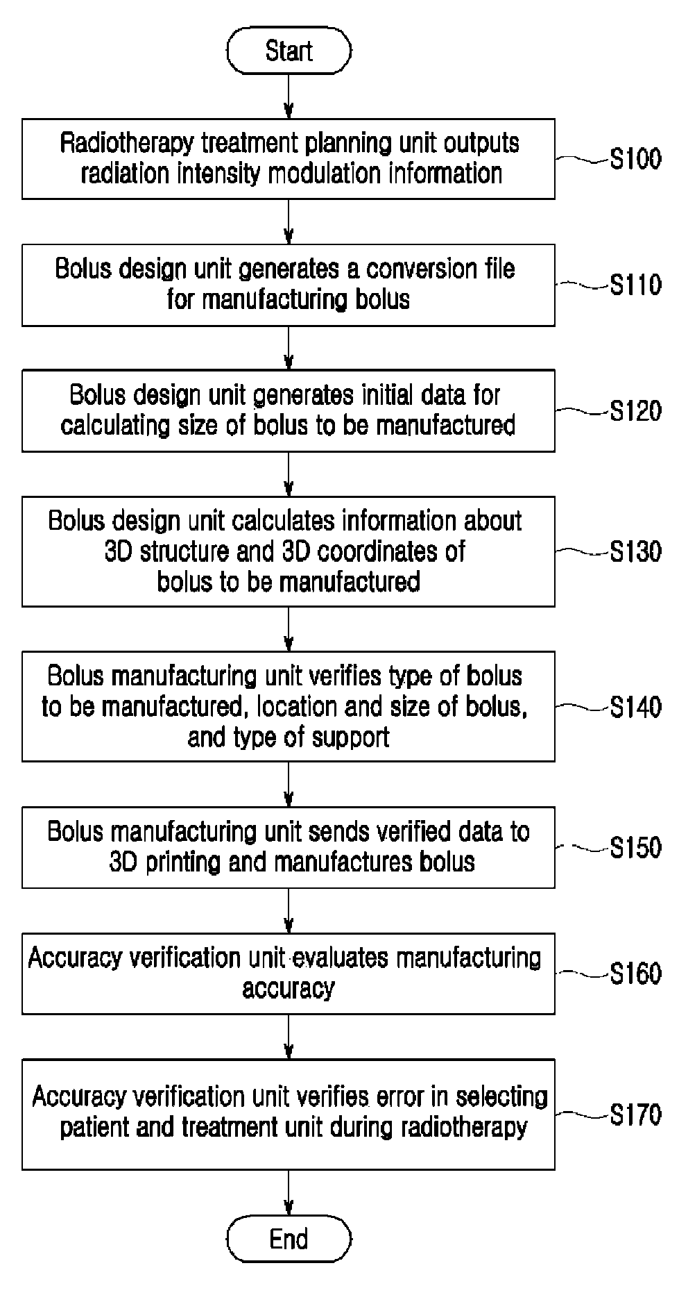
  • Method and apparatus for manufacturing radiation intensity bolus
  • Method and apparatus for manufacturing radiation intensity bolus
  • Method and apparatus for manufacturing radiation intensity bolus

Examples


Embodiment Construction

[0042]Hereinafter, embodiments of a method and apparatus for manufacturing a radiation intensity bolus according to the present disclosure are described with reference to the accompanying drawings.

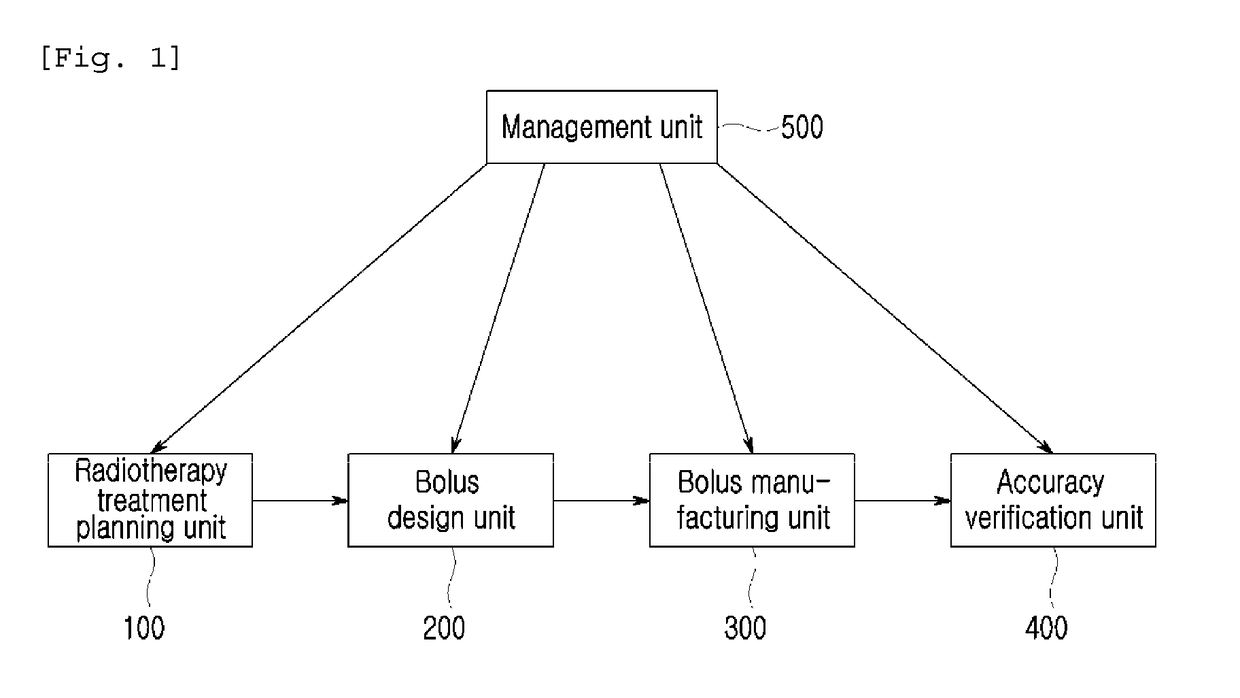
[0043]FIG. 1 is a block diagram of an apparatus for manufacturing a radiation intensity bolus for implementing a method for manufacturing a radiation intensity bolus according to the present disclosure. The apparatus includes a radiotherapy treatment planning unit 100, a bolus design unit 200, a bolus manufacturing unit 300, an accuracy verification unit 400, and a management unit 500.

[0044]The function of each of the blocks of the apparatus for manufacturing a radiation intensity bolus for implementing a method for manufacturing a radiation intensity bolus according to the present disclosure is described below with reference to FIG. 1.

[0045]The radiotherapy treatment planning unit 100 computes a 3D radiation dose distribution calculated using a radiotherapy treatment planning apparatus or...


PUM

PropertyMeasurementUnit
sizeaaaaaaaaaa
structureaaaaaaaaaa
distance inverse square lawaaaaaaaaaa

Abstract

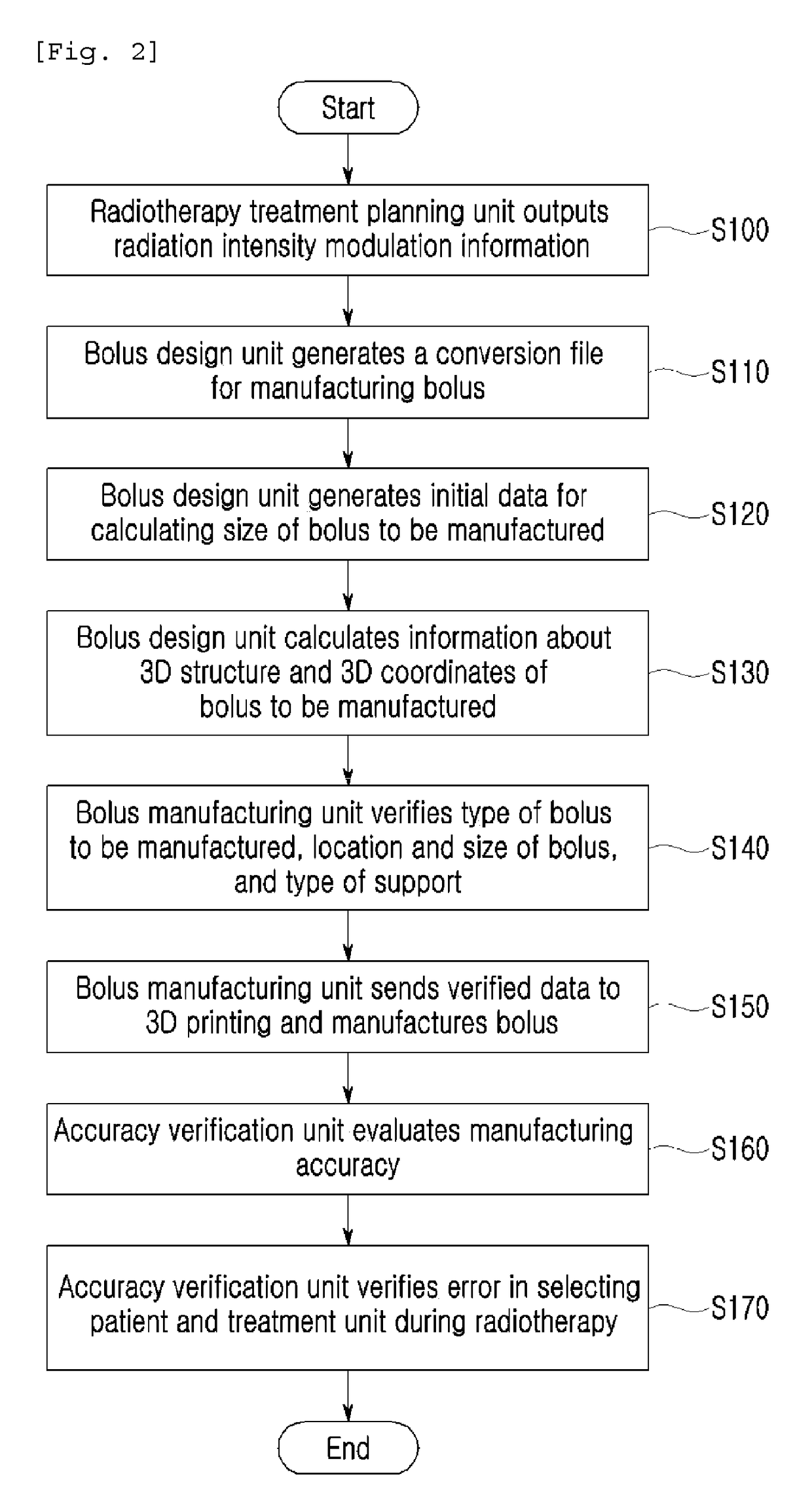
Disclosed are a method and an apparatus for manufacturing a radiation intensity bolus. The method comprises the steps of: (a) calculating, by a radiotherapy treatment planning unit, a received 3D radiation dose distribution, planning a bolus to be manufactured, and outputting radiation intensity modulation information; (b) receiving, by a bolus design unit, the radiation intensity modulation information, generating a conversion file for manufacturing bolus, and outputting information about a 3D structure of the bolus to be manufactured; (c) receiving, by a bolus manufacturing unit, the conversion file for manufacturing bolus, verifying a type, location, and size of the bolus to be manufactured, sending the verified data to a 3D printer, and manufacturing the bolus; and (d) obtaining, by an accuracy verification unit, information about a 3D structure of the manufactured bolus and evaluating manufacturing accuracy by comparing the information about the 3D structure of the manufactured bolus with the information about the planned bolus.

Description

TECHNICAL FIELD[0001]The present disclosure relates to a method and apparatus for manufacturing a radiation intensity bolus, and more particularly, to a method and apparatus for manufacturing a radiation intensity bolus, which are capable of manufacturing a radiation intensity bolus so that the bolus can be made in a desired shape using a 3D printer based on radiation dose modulation information obtained by calculating a radiation dose in radiotherapy.BACKGROUND ART[0002]In general, a radiation intensity bolus is a material that is placed in the center of a radiation beam, or placed in contact with or inserted into the body of a patient in order to modulate a radiation dose distribution of radiotherapy.[0003]The radiation intensity bolus is used to increase a tumor radiation dose and to protect surrounding normal tissues by modulating the intensity of radiation in radiotherapy. It is used for electron beam, X-ray, proton, and particle beam radiotherapies. Particularly for the proton...

Claims


Application Information

Patent Timeline
Patent Type & Authority Patents(United States)
IPC IPC(8): G05B19/418A61N5/10B33Y80/00B22F3/105G21K1/04G21K1/10B29C64/00
CPCG05B19/41875A61N5/10A61N5/1075B33Y80/00A61N5/103A61N2005/1087Y02P10/295A61N2005/1096B22F3/1055B29C64/00G21K1/046G21K1/10A61N2005/1095Y02P10/25B22F10/40B22F12/90H05G1/30A61B6/10G01T1/161
Inventor JU, SANG GYU
Owner SAMSUNG LIFE PUBLIC WELFARE FOUND
Learn More