Visual counting system

a counting system and counting system technology, applied in the field of visual counting system, can solve the problems of increasing the cost of automated pill counters, affecting the aesthetics of such devices, and utilizing complex mechanisms and complex electronic control, so as to reduce the size, improve the aesthetics of such devices, and reduce background noise.

Active Publication Date: 2018-05-01
MANREX AUSTRALIA
View PDF24 Cites 7 Cited by
  • Summary
  • Abstract
  • Description
  • Claims
  • Application Information

AI Technical Summary

Benefits of technology

[0012]The present visual counting system is different from existing counting technologies currently on the market. Existing vision based counting solutions contain a backlit counting surface with camera on the opposite side, typically mounted above the counting surface. The present device places the camera and preferably an infrared light source below the counting surface. This offers the unique advantage of not having to mount a camera above the counting surface which reduces the size and improves the aesthetic characteristics of such a device. In a preferred embodiment, the camera does not contain an IR filter commonly found on most standard cameras. The counting surface preferably consists of a dark colored IR transmissive material optionally covered by a protective layer of glass. The dark color reduces background noise, and the IR transmissive material allows the IR illumination to pass through and reflect off of the bottom side of the pills back to the camera. The image is captured and then processed to determine the number of pills on the surface. Other wavelengths of light may also work with the appropriate supporting hardware (camera, counting surface, and light source).

Problems solved by technology

Such devices, however, typically utilize complex mechanisms and complex electronic control.
This complexity tends to drive up the cost of automated pill counters, making them expensive to build, purchase, and maintain.

Method used


Image

  • Visual counting system
  • Visual counting system
  • Visual counting system

Examples


Embodiment Construction

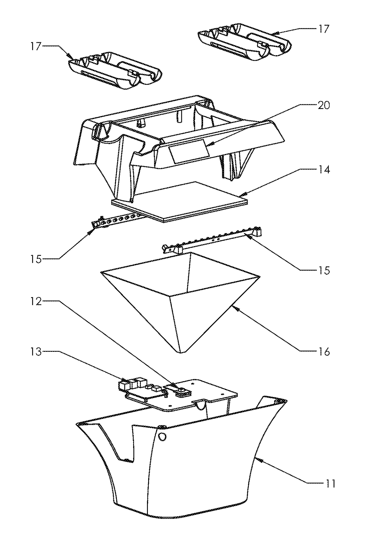
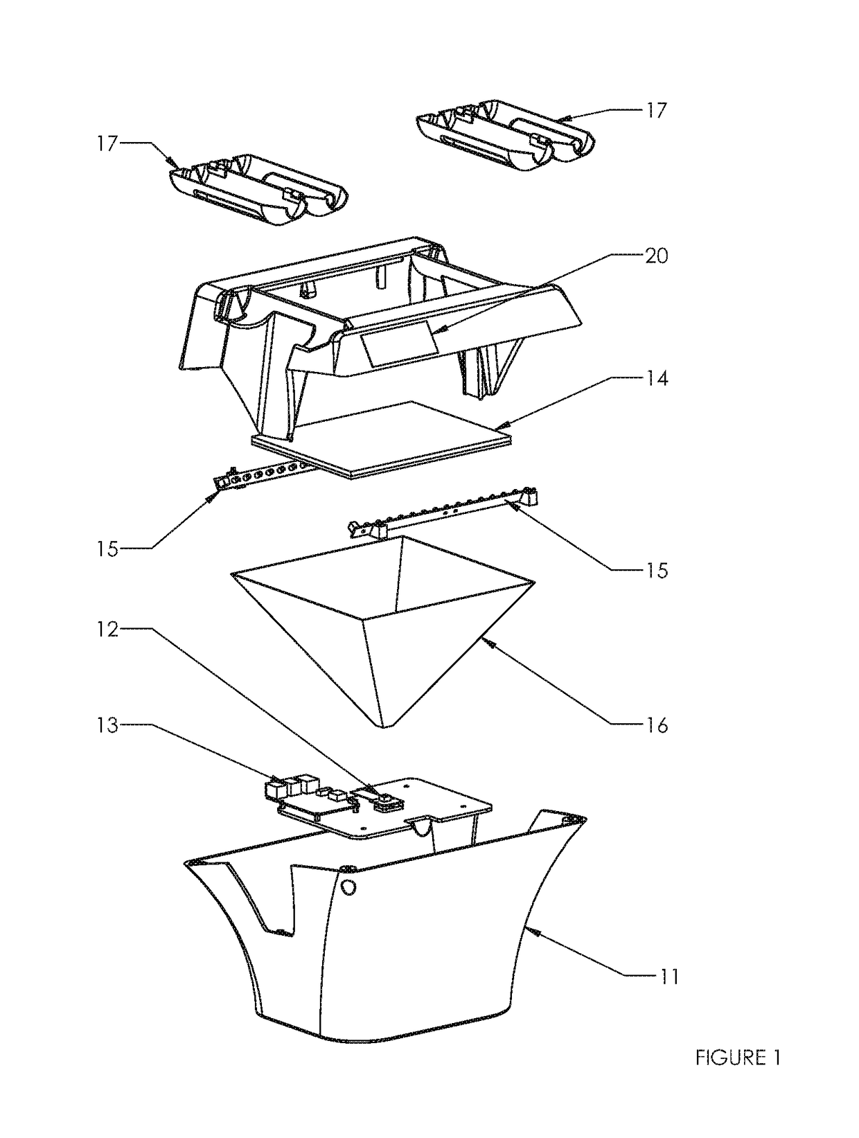
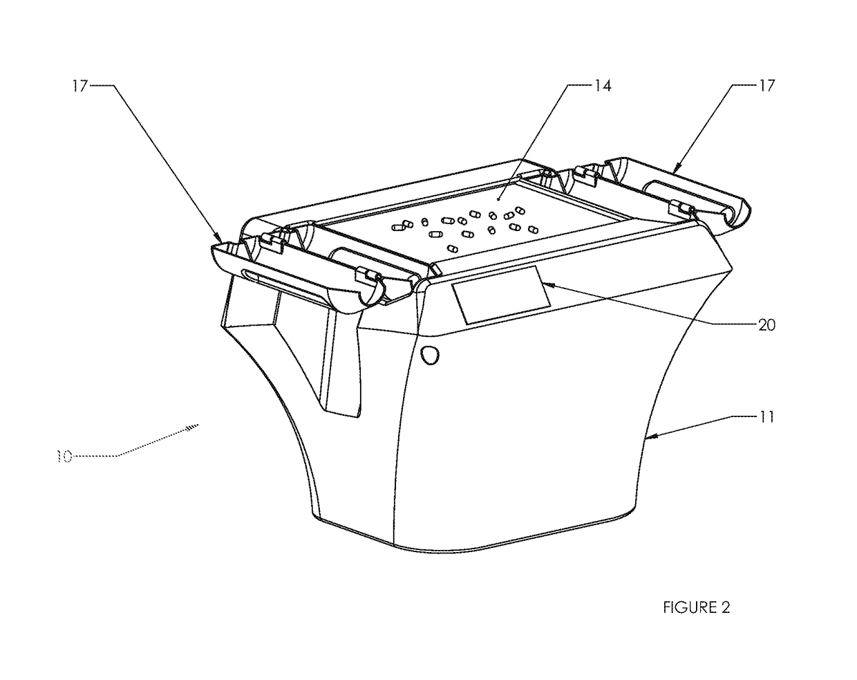
[0021]In a preferred embodiment, the device 10 consists of a housing 11 with an upper counting surface 14. The housing 11 houses a camera 12, a light source 15, and an image processor or computer 13, these components being located beneath the counting surface 14. Pills or small items to be counted are poured onto the counting surface 14 and illuminated from below via the light source 15. The light bounces off the pills, reflecting back the camera 12 which captures an image. The computer 13 runs an algorithm which calculates the number of pills on the counting surface 14.

[0022]FIG. 1 illustrates an exploded view of a preferred embodiment of the present invention. Within the housing 11, there is a camera 12 and computer 13 capable of processing the images taken by the camera 12. The computer 13 may also be programmed to interface with pharmacy management systems, this capability being explained in further detail herein. The camera 12 may be mounted in any desired location within the h...


PUM


Abstract

A low-profile visual counting system is provided and designed to count pills or other small discrete objects. This technology is vision based, which allows a pharmacist or other user to pour pills onto a counting surface in a single layer, and then the device tells the user how many pills are on that surface. The present device places the camera and preferably an infrared light source below the counting surface. This offers the unique advantage of not having to mount a camera above the counting surface which reduces the size and improves the aesthetic characteristics of such a device. The image is captured and then processed to determine the number of pills on the surface. This system may be interfaced with other networks, terminals, and existing pharmacy management systems.

Description

BACKGROUND OF THE INVENTION[0001]Pill counting in pharmacies is necessary for the filling of prescriptions. Heretofore, this counting process involved a pharmacist or other qualified pharmacy employee pouring out a quantity of pills or capsules from a supply container and manually counting the required number of pills. The excess units are then returned to the supply bottle, while the proper number of counted units is poured into a vial to be presented to the patient for whom the prescription was written.[0002]More recently, a variety of devices have been developed and utilized to count pills or capsules automatically, thus eliminating or reducing the need for manual counting. These devices also serve to decrease human error and improve counting accuracy. Such devices, however, typically utilize complex mechanisms and complex electronic control. This complexity tends to drive up the cost of automated pill counters, making them expensive to build, purchase, and maintain.[0003]While m...

Claims


Application Information

Patent Timeline
Patent Type & Authority Patents(United States)
IPC IPC(8): A61J7/02G06M11/00G06K9/00G06M1/02H04N5/33H04N5/225G06V20/66
CPCA61J7/02G06K9/00G06M1/022H04N5/33H04N5/2252H04N5/2256G06M11/00A61J2205/60A61J2200/70G16H30/40G16H20/13G06V20/66H04N23/56H04N23/51A61J7/00G06F18/00
Inventor THOMPSON, DEREK WILLIAMBURNEY, BRIAN MARSHALLDEAKINS, BRYANT JAMESMARTIN, COREY SPENCERJONES, MICHAELISRAEL, STEVEN CRAIG
Owner MANREX AUSTRALIA
Why Eureka
Try Eureka