Method and device for time-resolved pump-probe electron microscopy

a technology of electron microscopy and pumpprobe, which is applied in the field of time-resolved pumpprobe electron microscopy, can solve the problems of reference set, controllability, structural complexity of optical delay line for adjusting, and conventional techniques have disadvantages, and achieve high accuracy, influence the accuracy of phase recovery, and precise temporal resolution

Inactive Publication Date: 2018-05-22
MAX PLANCK GESELLSCHAFT ZUR FOERDERUNG DER WISSENSCHAFTEN EV
View PDF9 Cites 0 Cited by
  • Summary
  • Abstract
  • Description
  • Claims
  • Application Information

AI Technical Summary

Benefits of technology

[0032]As a main advantage of the invention, the photonic pump pulse is created by the electron probe pulse, so that the temporal relationship of both pulses when arriving at the sample is determined. The temporal relationship is determined by geometric quantities, in particular a distance between the photonic lattice structure and the sample, a length of the pump pulse path, a velocity of the photonic pump pulse and / or a velocity of the electron probe pulse. Thus, the inventors have shown that it possible that each individual electron probe pulse imposes its own time-reference. Advantageously, the stochastic behaviour of the electron probe pulses in comparison with an external laser emission as occurring with the conventional techniques is effectively omitted.
[0033]According to the invention, a method and / or apparatus for measuring the ultrafast response of matter and systems using electron sources is provided. In contrast to the conventional methodology incorporating ultrashort laser pulses as pumps and time references (4D electron microscopy and diffraction), the invention shows the possibility of a pump-probe method without utilizing a laser source. By introducing the photonic lattice structure, i. e. a structure capable of producing coherent pulse-shaped optical fields in interaction with the arriving electron, and focusing the generated pulse-shaped optical field into the structure, the sample is pumped into a dynamical evolution. The arriving electron is then used to probe the sample at a certain delay with respect to the incident photons on the sample.
[0034]Advantageously, an electron-photon pump-probe experimental setup is obtained, which can be driven by only individual electron sources, without any laser illumination. Furthermore, with this setup the statistical distribution of individual electron probe pulses is effectively omitted, since each electron imposes its own time reference. A precise temporal resolution can be obtained as short as few femtoseconds and less (if pulse compression is implemented). The term “pump-probe electron microscopy” refers to any electron microscopy technique, wherein the sample is irradiated with an electron pulse and a photon pulse having a predetermined temporal relationship relative to each other.
[0035]Generally, the temporal relationship of the photonic pump pulse and the electron probe pulse is the time difference between the peaks of the photonic pump pulse and electron probe pulse. As the velocity of the photonic pump pulse (speed of light) is larger than the velocity of the electron probe pulse, the photonic pump pulse can arrive at the sample before the electron probe pulse as it is usually requested for a pump-probe setup of time resolved microscopy. Thus, the temporal relationship of the photonic pump pulse and the electron probe pulse preferably is a positive time delay of the electron probe pulse relative to the photonic pump pulse. However, the term temporal relationship also covers a simultaneous arrival time or even a negative time delay, wherein the peak of the photonic pump pulse arrives after the peak of the electron probe pulse at the sample.
[0036]The negative time delay can be obtained with the case of extremely relativistic electrons, which allows that the electron arrives sooner at the sample than the photons. Negative time delays can be considered for any pump-probe measurement for the following reason. Since both the photonic pump pulse and the electron probe pulse have tails (some broadening in time steps), they start exciting the sample even before the peak of the excitation reaches the structure. This means that pump can still be ahead of the probe, but influencing the structure in a way that probe senses it. Depending on the practical application of the invention, the accuracy of any correlation function to be extracted e. g. from the experimental spectra can be influenced. Without the negative delay components, the Fourier transformed correlation functions would be obtained from the positive delays only. Since in principle the positive- and negative-delay parts of the spectra are not similar, this might influence the accuracy of phase recovery by only considering positive delay. Thus, negative time delay would be preferential in the purpose to characterize the phase by Fourier transform analysis with high accuracy.
[0037]In practice, the method can be conducted with one single pair of a photonic pump pulse and an electron probe pulse, or a series of pairs of a photonic pump pulse and an electron probe pulse, wherein each electron probe pulse creates its associated photonic pump pulse. Thus, according to a preferred embodiment of the invention, the steps of irradiating the sample with the photonic pump and electron probe pulses and detecting the sample response are repeated with varying time delays of the electron probe pulse relative to the pump pulse, e. g. for investigating transient dynamic processes on an atomic level.

Problems solved by technology

Furthermore, the conventional techniques have disadvantages in terms of controllability and structural complexity of the optical delay line for adjusting the delay between the electron probe pulse and photon pump pulse.
However, still the time reference set by the arrival time of the laser in comparison with the electron arrival time is limited by the choice of the synchronization technique between the compressive electron-optical element and the laser source, and even a clear statement on the possible final limit on the temporal resolution due to the time jitter is not present in the literature, mainly because of the lack of theoretical models [7].
Although the single-electron mode in comparison with the single-shot mode has offered a better temporal resolution due to the omission of the space-charge effect, still the single electron mode suffers from the stochastic behaviour of the assembly of at least 107 individual electron pulses needed to carry out the experiment, in comparison with the time reference set by the laser pump illuminating the sample.

Method used


Image

  • Method and device for time-resolved pump-probe electron microscopy
  • Method and device for time-resolved pump-probe electron microscopy
  • Method and device for time-resolved pump-probe electron microscopy

Examples


Embodiment Construction

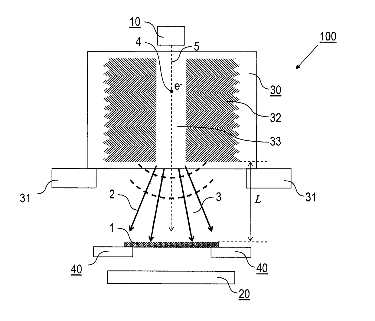
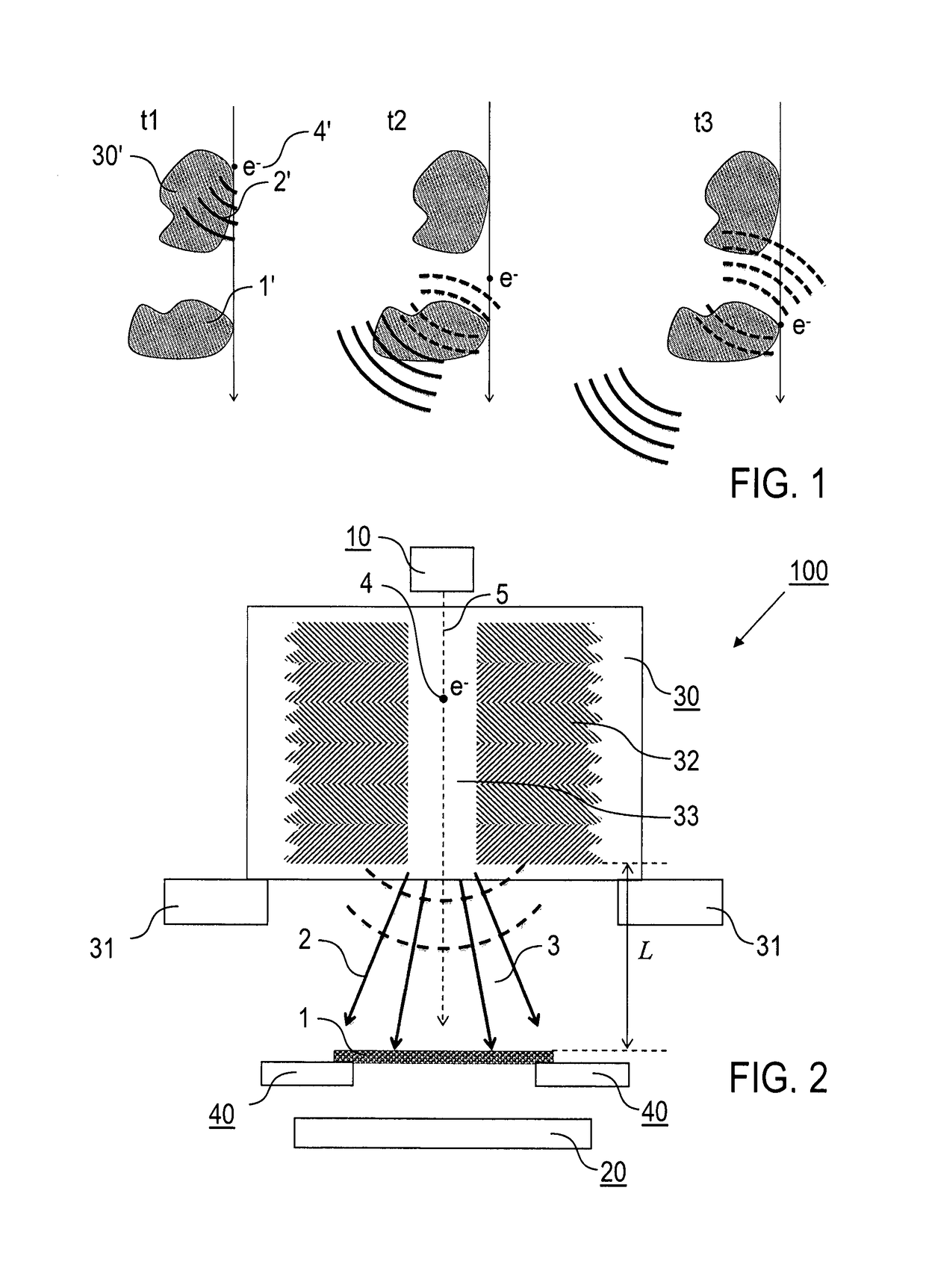
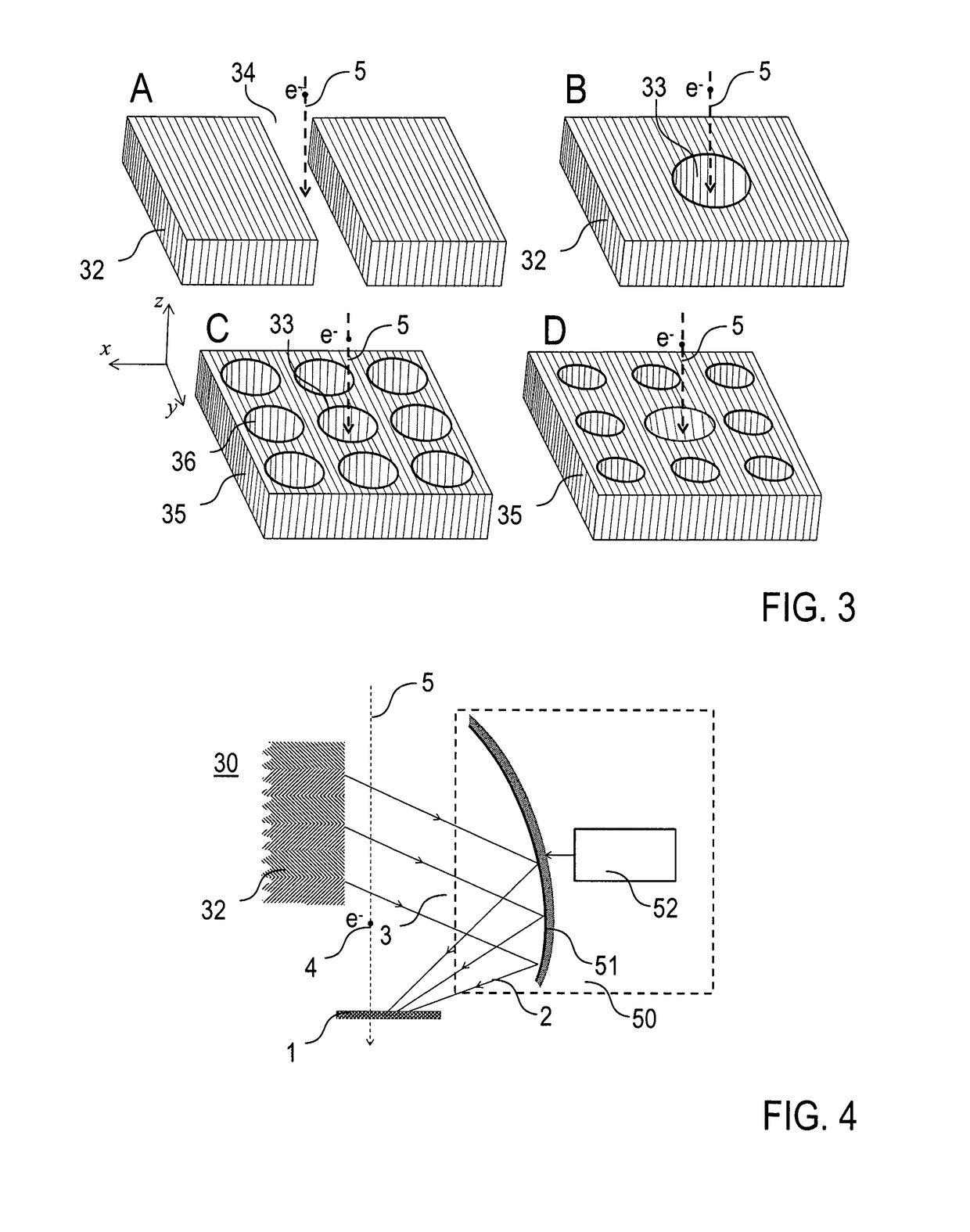
[0059]Features of preferred embodiments of the invention are described here with particular reference to the creation of photonic pump pulses in an electron microscope using a photonic lattice structure. Details of the electron microscope and the operation thereof, the sample preparation and the signal processing and analysis are not described as far as they are known as such from conventional techniques. Exemplary reference is made to methods of time-resolved pump-probe electron microscopy. It is emphasized that the invention is not restricted to these examples, but rather can be used with other applications combining electron irradiation and photonic irradiation at a sample as well.

[0060]According to a preferred embodiment of the invention, the Smith-Purcell effect is used for creating a photonic reference pulse at a defined flexible reference time, which is independent of the stochastic behavior of a single-electron probe pulse for investigating a sample. The Smith-Purcell emissi...


PUM

PropertyMeasurementUnit
distanceaaaaaaaaaa
thicknessaaaaaaaaaa
distanceaaaaaaaaaa

Abstract

A method of time-resolved pump-probe electron microscopy, comprises the steps of irradiating a sample (1) with a photonic pump pulse (2) being directed on a pump pulse path (3) from a photonic source to the sample (1), irradiating the sample (1) with an electron probe pulse (4) being directed on an electron pulse path (5) from an electron pulse source (10) to the sample (1), wherein the photonic pump pulse (2) and the electron probe pulse (4) arrive at the sample (1) with a predetermined temporal relationship relative to each other, and detecting a sample response to the electron probe pulse (4) irradiation with a detector device (20), wherein the photonic source comprises a photonic lattice structure (30) being arranged adjacent to the electron pulse path (5), and the photonic pump pulse (2) is created by an interaction of the electron probe pulse (4) with the photonic lattice structure (30). Furthermore, an electron microscopy apparatus, configured for time-resolved pump-probe electron microscopy, and a sample supply device (200) for an electron microscopy apparatus (100) are described.

Description

CROSS-REFERENCE TO RELATED APPLICATIONS[0001]This application is the U.S. National Phase Application of PCT / EP2015 / 001509, filed Jul. 22, 2015, which claims priority from EP 14002946.3, filed Aug. 25, 2014, the contents of which applications are incorporated herein by reference in their entireties for all purposes.FIELD OF THE INVENTION[0002]The present invention relates to a method of time-resolved pump-probe electron microscopy, wherein a sample is subjected to a photonic pump pulse and an electron probe pulse. Furthermore, the invention relates to an electron microscopy apparatus, which is adapted for time-resolved pump-probe electron microscopy. Applications of the invention are available in electron microscopy techniques, like e. g. diffraction, imaging and / or spectroscopy methods.BACKGROUND OF THE INVENTION[0003]In the present specification, reference is made to the following publications illustrating conventional techniques.[0004][1] WO 2005 / 098895 A2;[0005][2] A. Yurtsever e...

Claims


Application Information

Patent Timeline
Patent Type & Authority Patents(United States)
IPC IPC(8): G01N23/00H01J37/22H01J37/244H01J37/26
CPCH01J37/228H01J37/226H01J37/244H01J37/26H01J2237/2626H01J2237/2445H01J2237/24475H01J2237/24585G01N23/2251
Inventor TALEBI SARVARI, NAHID
Owner MAX PLANCK GESELLSCHAFT ZUR FOERDERUNG DER WISSENSCHAFTEN EV
Why Eureka
Try Eureka