
Radiation tolerant, analog latch peak current mode control for power converters

a technology of power converters and latches, applied in the direction of electric variable regulation, process and machine control, instruments, etc., can solve the problems of electronic noise and signal spikes, special design challenges, and certain performance tradeoffs

Active Publication Date: 2018-05-22
CRANE ELECTRONICS INC
View PDF298 Cites 3 Cited by
  • Summary
  • Abstract
  • Description
  • Claims
  • Application Information

AI Technical Summary

Benefits of technology

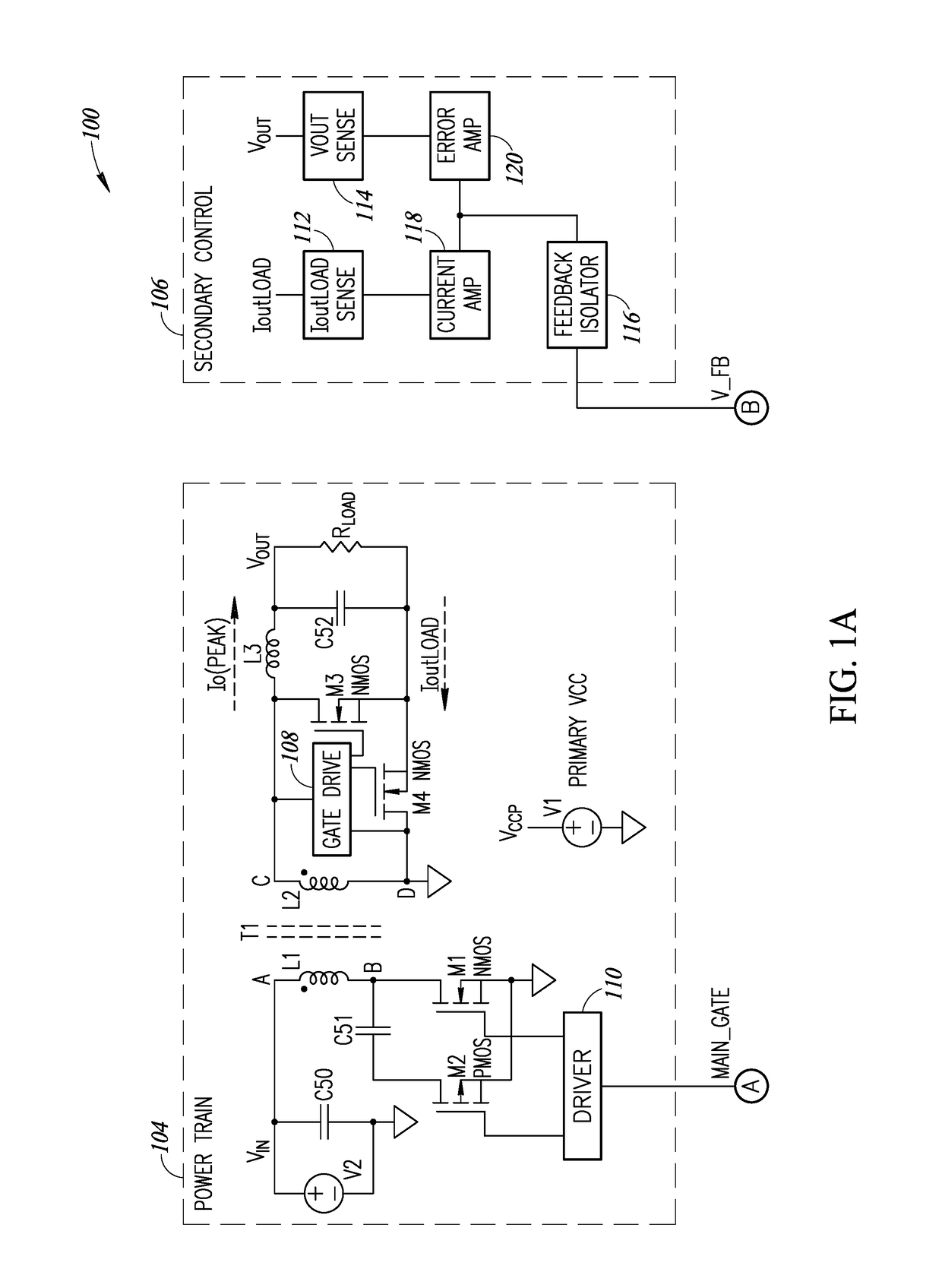
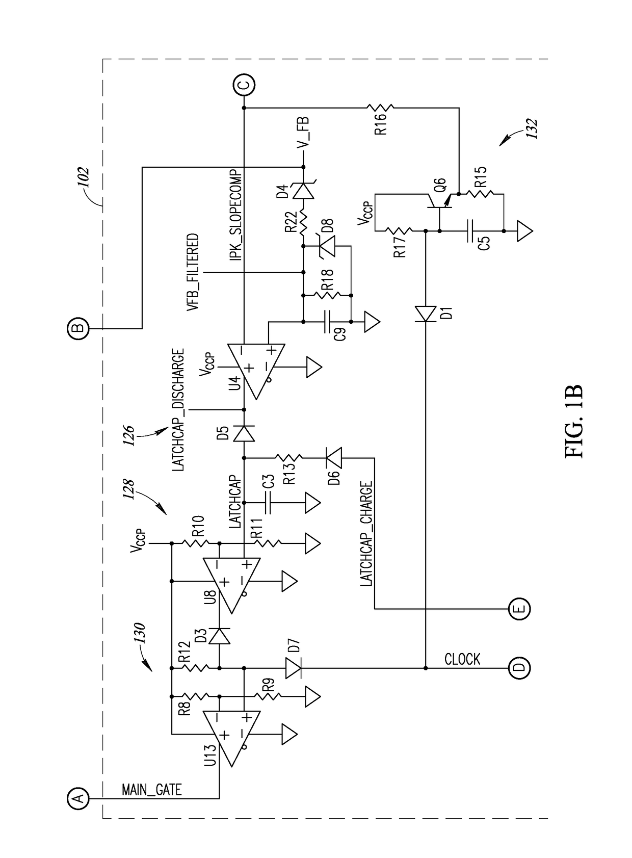
The patent text describes a peak current mode control (PCMC) controller for a power converter that uses analog circuits to control the power converter's switches. The PCMC controller includes an analog latch circuit, a peak current detector circuit, a clock circuit, and an analog gate circuit. The analog latch circuit has an input and an output and is controlled by a latching capacitor. The peak current detector circuit compares a current sensor signal to an error control signal and, when the current sensor signal exceeds the error control signal, causes the latching capacitor to discharge. The clock circuit generates a clock signal and a charge signal, which are used to selectively charge the latching capacitor. The analog gate circuit has an input operatively coupled to the clock signal and the output of the analog latch circuit and provides a control signal to the power converter's switches. The PCMC controller helps to improve the power converter's efficiency and stability.

Problems solved by technology

These constraints require certain performance tradeoffs.
Environments with high levels of ionizing radiation create special design challenges.
A single charged particle can knock thousands of electrons loose, causing electronic noise and signal spikes.
In the case of digital circuits, this can cause results which are inaccurate or unintelligible.
This can be a particularly serious problem in the design of components for satellites, spacecraft, aircraft, power stations, etc.

Method used


Image

  • Radiation tolerant, analog latch peak current mode control for power converters
  • Radiation tolerant, analog latch peak current mode control for power converters
  • Radiation tolerant, analog latch peak current mode control for power converters

Examples


Embodiment Construction

[0022]In the following description, certain specific details are set forth in order to provide a thorough understanding of various disclosed implementations. However, one skilled in the relevant art will recognize that implementations may be practiced without one or more of these specific details, or with other methods, components, materials, etc. In other instances, well-known structures associated with computer systems, server computers, and / or communications networks have not been shown or described in detail to avoid unnecessarily obscuring descriptions of the implementations.

[0023]Unless the context requires otherwise, throughout the specification and claims that follow, the word “comprising” is synonymous with “including,” and is inclusive or open-ended (i.e., does not exclude additional, unrecited elements or method acts).

[0024]Reference throughout this specification to “one implementation” or “an implementation” means that a particular feature, structure or characteristic de...


PUM


Abstract

Systems and methods for providing peak current mode control (PCMC) for power converters using discrete analog components. Peak current mode control functionality for latching, set, reset, clocking and slope compensation is provided via available analog components that provide improved performance, design flexibility, reliability, and radiation tolerance. Discrete analog components may include analog comparators, resistors, capacitors, diodes, etc.

Description

BACKGROUNDTechnical Field[0001]The present disclosure generally relates to controllers for power converters.Description of the Related Art[0002]DC / DC converters are a type of power supply which converts an input DC voltage to a different output DC voltage. Such converters typically include a transformer that is electrically coupled via a switching circuit between a voltage source and a load. Converters known as forward converters include at least one main switch connected between the voltage source and the primary winding of the transformer to provide forward power transfer to the secondary winding of the transformer when the switch is on and conducting. A metal oxide semiconductor field effect transistor (MOSFET) device is typically used for the one or more main switches.[0003]Power converter designs are often constrained by various requirements, such as efficiency, input voltage range, output voltage, power density, and footprint area. These constraints require certain performance...

Claims


Application Information

Patent Timeline
Patent Type & Authority Patents(United States)
IPC IPC(8): H02M1/08H02M1/44H02M3/156H02M3/07H02J3/18H02M1/42H05B33/08H05B44/00
CPCH02M3/07H02M1/08H02M3/156H02M1/4208H05B33/0845H02J3/18H05B33/0815H02M1/44H02M3/33592H02M3/33507Y02B70/10
Inventor LAM, CUONNGUYEN, HACHNGUYEN, KHOAODELL, PETERSONG, SOVANN
Owner CRANE ELECTRONICS INC
Learn More