Double-sided tangential cutting insert and cutting tool system using the same

a cutting tool and indexable technology, applied in the direction of manufacturing tools, metal-working equipment, milling equipment, etc., can solve the problems of difficult to effectively balance on the required surface finish and the perpendicularity between the machined surface and the machined wall on the workpi

Active Publication Date: 2018-05-29
KENNAMETAL INC
View PDF184 Cites 10 Cited by
  • Summary
  • Abstract
  • Description
  • Claims
  • Application Information

AI Technical Summary

Benefits of technology

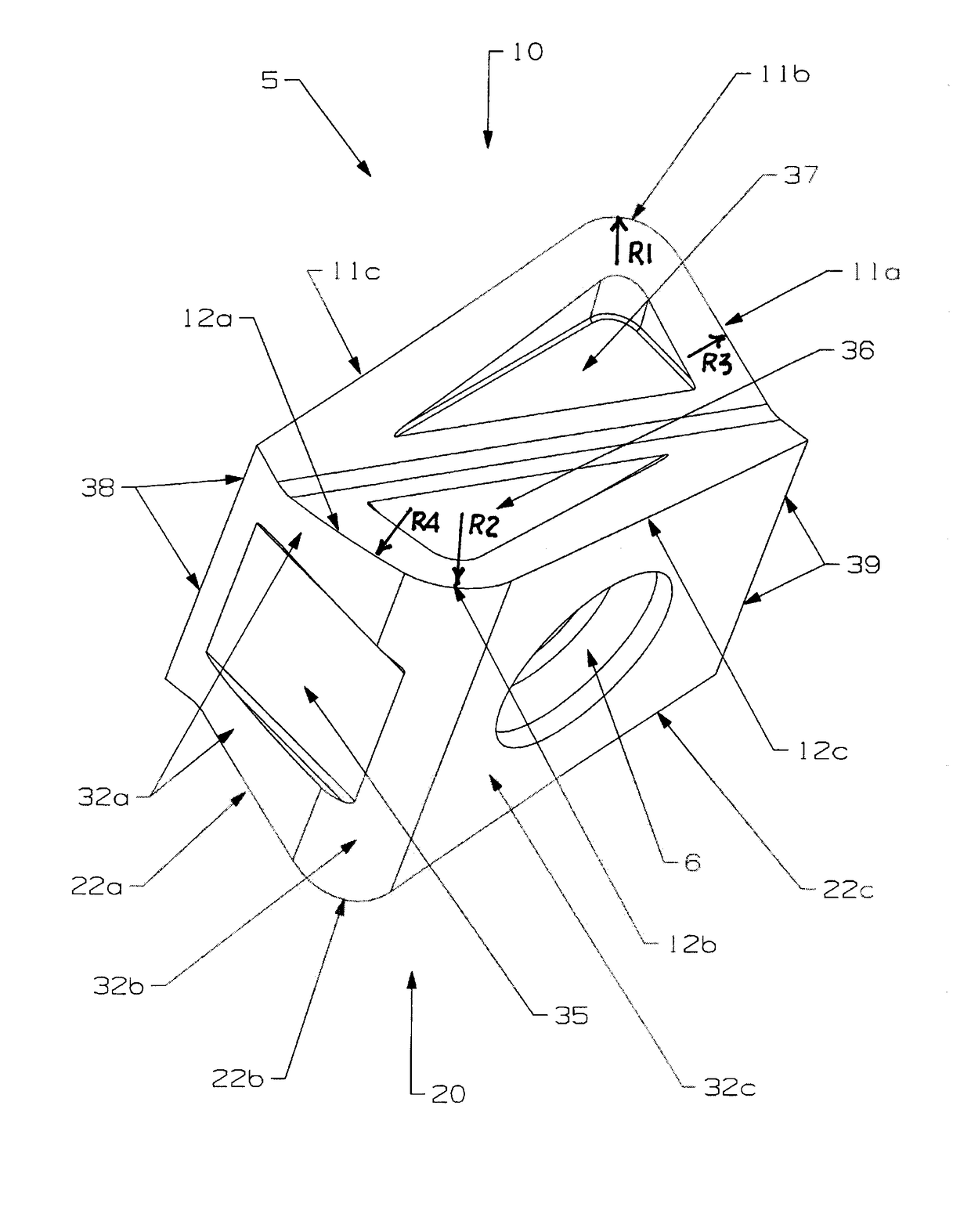
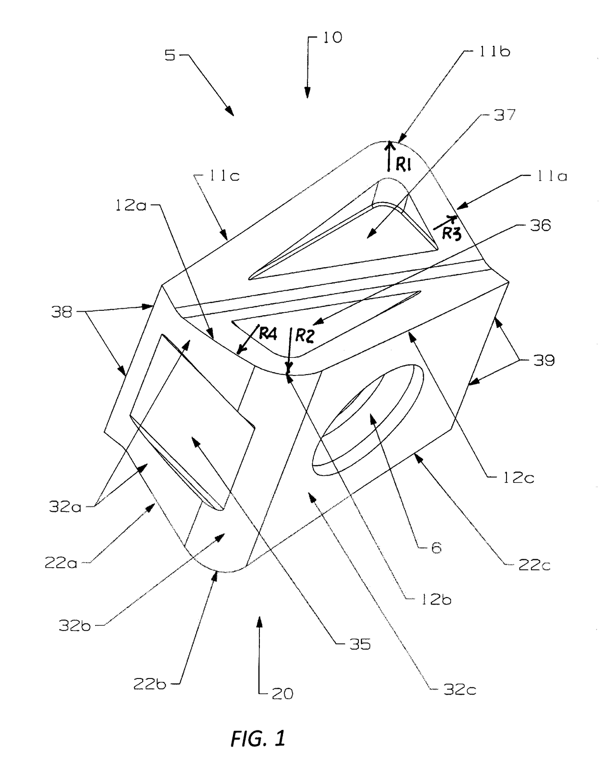
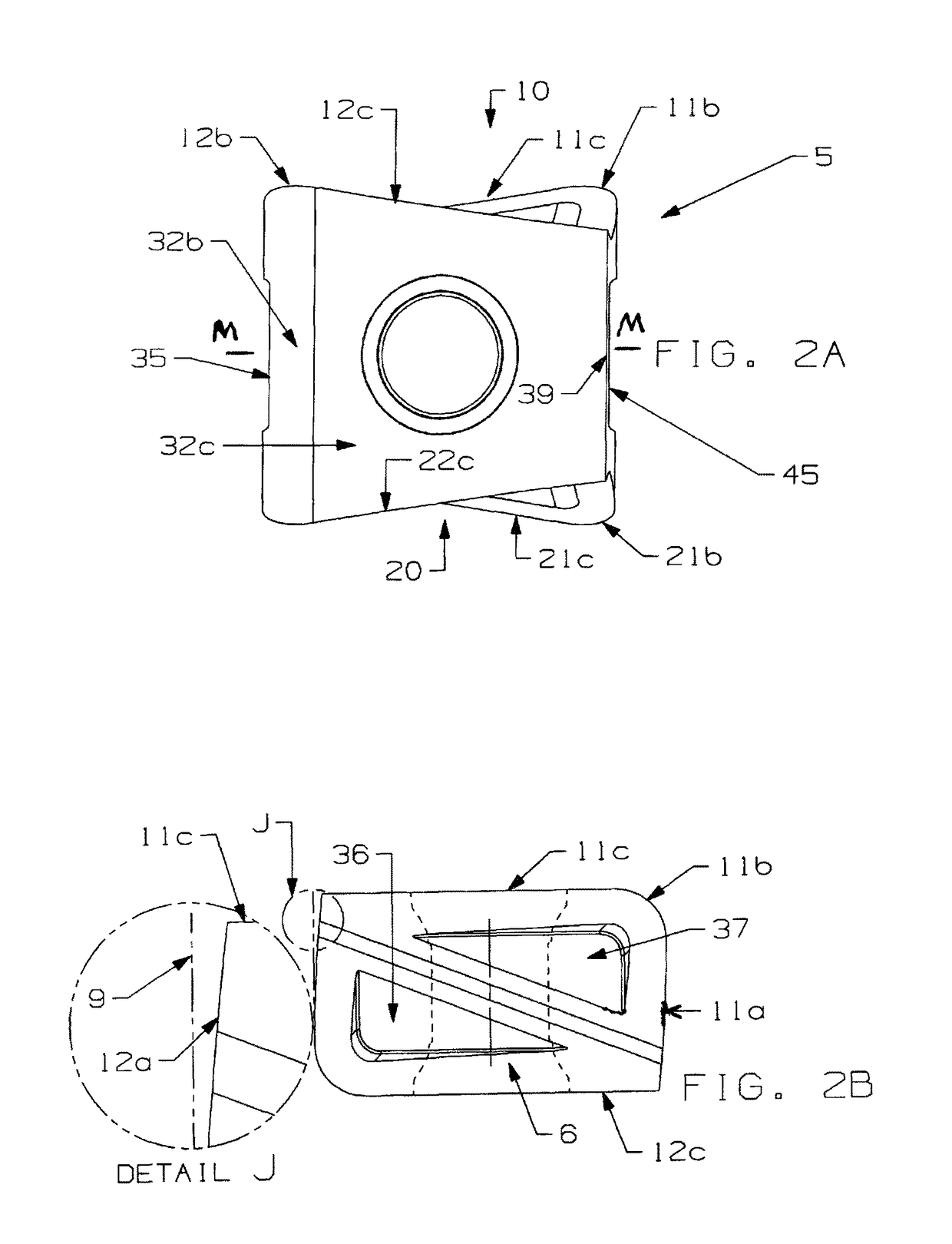
[0006]The two identical opposing cutting rake surfaces of the double-sided tangential cutting insert of the present invention have a unique peripheral profile comprising mainly a pair of identical opposing substantially straight cutting edges, a pair of opposing arcuate cutting edges with a regular radius and a pair of opposing convex minor cutting edges with a much larger radius (as viewed from a direction normal to the cutting rake surface). One advantage of a convex minor cutting edge with a much larger radius associated with a convex minor side face is to guarantee the surface finish of machined surface as well as the perpendicularity between the machined surface and machined wall on the workpiece under some heavy cutting conditions. Another advantage of a convex minor cutting edge having a large radius is that the large curvature radius, as compared with a straight minor cutting edge perpendicular to a straight main cutting edge, can adapt to some undesirable machining processes such as, for example, tool holder deflections during machining and tolerance variations from product manufacturing.

Problems solved by technology

The drawbacks with the kinds of cutting inserts disclosed in these patents include a difficulty to effectively balance on the required surface finish and the perpendicularity between the machined surface and machined wall on the workpiece which occurs, for example, in a slot milling, largely due to the complex cutting edge geometry in particular on the minor cutting edges formed between the cutting rake face and the minor side face.

Method used


Image

  • Double-sided tangential cutting insert and cutting tool system using the same
  • Double-sided tangential cutting insert and cutting tool system using the same
  • Double-sided tangential cutting insert and cutting tool system using the same

Examples


Embodiment Construction

[0037]In the present description of non-limiting specific embodiments and in the claims, other than in the operating examples or where otherwise indicated, all numbers expressing quantities or characteristics of ingredients and products, processing conditions, and the like are to be understood as being modified in all instances by the term “about”. Accordingly, unless indicated to the contrary, any numerical parameters set forth in the following description and the attached claims are approximations that may vary depending upon the desired properties one seeks to obtain in the apparatus and methods according to the present disclosure. At the very least, and not as an attempt to limit the application of the doctrine of equivalents to the scope of the claims, each numerical parameter should at least be construed in light of the number of reported significant digits and by applying ordinary rounding techniques.

[0038]Any patent, publication, or other disclosure material, in whole or in ...


PUM


Abstract

A double-sided tangential cutting insert, as well as a tool holder system that carries a plurality of the double-sided tangential cutting inserts, that has a peripheral side shape, as viewed from one of said cutting rake faces, that includes a pair of generally identical opposing main cutting edges wherein each of the main cutting edge comprises a substantially straight main cutting edge portion and an adjoining convex main cutting edge portion. The convex main cutting edge portion is truncated by an adjacent convex minor side face so as to define a generally sharp edge and a point of truncation. The peripheral side shape further includes a pair of opposing full nose cutting edges with a nose cutting radius; and a pair of opposing convex minor cutting edges with a minor cutting edge radius. The minor cutting edge radius is at least about four times greater than the nose cutting radius.

Description

BACKGROUND OF THE INVENTION[0001]The present disclosure is directed to an indexable double-sided tangential cutting insert and a cutting tool system, which use such double-sided tangential cutting inserts, for a variety of rotary milling applications. In one non-limiting specific embodiment, indexable double-sided tangential cutting inserts according to the present invention are particularly useful in peripheral rotary milling applications for machining difficult-to-machine materials. In another non-limiting specific embodiment, indexable double-sided tangential cutting inserts according to the present invention are uniquely useful in peripheral rotary milling applications that generate segmented chips, for instance, when machining cast-iron and alloys or medium to high carbon steels.[0002]A double-sided tangential milling cutting insert is generally defined as the cutting rake faces where the chip groove / chip breaker does not have a through fastener hole, or in other words, the thr...

Claims


Application Information

Patent Timeline
Patent Type & Authority Patents(United States)
IPC IPC(8): B23C5/20B23C5/08B23C5/22
CPCB23C5/2221B23C5/08B23C2200/0433B23C2220/36B23C2200/208B23C2200/367B23C2200/203B23C5/2204B23C2200/128B23C5/2213
Inventor FANG, XIANGDONG DANIELDUFOUR, JEAN-LUCBRUNETTO, LANCEMIZGALSKI, KENTWILLS, DAVIDCOPE, DAVID
Owner KENNAMETAL INC
Why Eureka
Try Eureka