
Control device for spark ignition type internal combustion engine

a technology of control device and internal combustion engine, which is applied in the direction of sparking plugs, combustion-air/fuel-air treatment, automatic control of ignition, etc., can solve the problems of catalyst melting, catalyst insufficient combustion, catalyst mixture insufficient combustion, etc., and achieve the effect of enhancing flame and sufficient combustion of fuel

Inactive Publication Date: 2018-06-05
DAIHATSU MOTOR CO LTD +1
View PDF17 Cites 0 Cited by
  • Summary
  • Abstract
  • Description
  • Claims
  • Application Information

AI Technical Summary

Benefits of technology

[0008]According to the present invention, even in a case in which the combustion of the air fuel mixture in the combustion chamber becomes unstable, it is possible to sufficiently combust the fuel by enhancing the flame by means of plasma generation. Accordingly, the problem of unburned fuel discharged to the outside of the cylinder is alleviated or eliminated.

Problems solved by technology

Meanwhile, in a case in which the air fuel mixture is insufficiently combusted resulting from the fact that the flame is weakened or the like in the process of combustion, a gas containing an unburned fuel component is exhausted from the cylinder to an exhaust passage, and reaches a three way catalyst for cleaning the exhaust gas.
Consequently, there is a concern that a spontaneous ignition (after-fire) of the fuel component may occur in a high temperature part of the exhaust passage, or oxidization of the fuel component may occur in the catalyst, thereby excessively increasing the temperature of the catalyst and causing the catalyst to be melted.

Method used


Image

  • Control device for spark ignition type internal combustion engine
  • Control device for spark ignition type internal combustion engine
  • Control device for spark ignition type internal combustion engine

Examples


Embodiment Construction

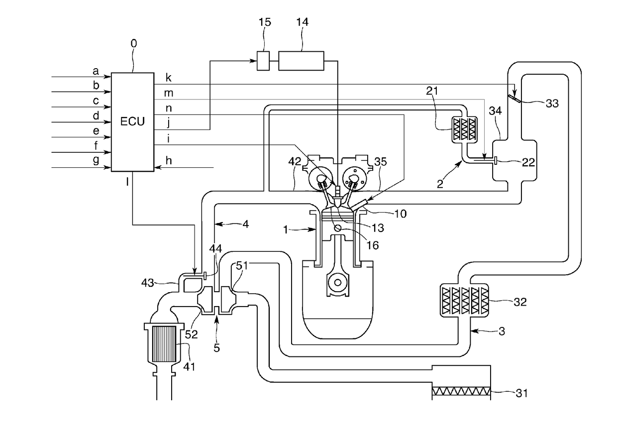
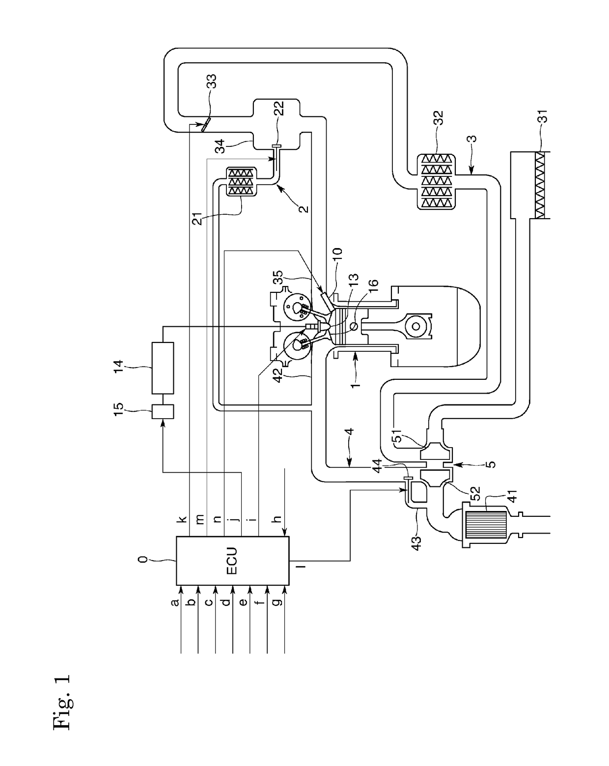
[0015]In the following, a description will be given of an embodiment of the present invention with reference to the accompanying drawings. FIG. 1 shows an outline of an internal combustion engine for a vehicle according to the present embodiment. The internal combustion engine is of an in-cylinder direct injection type, and is provided with a plurality of cylinders 1 (only one cylinder is shown in FIG. 1), injectors 10 for injecting fuel to the respective cylinders 1, intake passages 3 for supplying intake gas to the respective cylinders 1, exhaust passages 4 for exhausting exhaust gas from the respective cylinders 1, exhaust turbo superchargers 5 that supercharge intake gas flowing through the respective intake passages 3, and outside EGR (Exhaust Gas Recirculation) devices 2 that reflux EGR gas from the respective exhaust passages 4 to the respective intake passages 3.

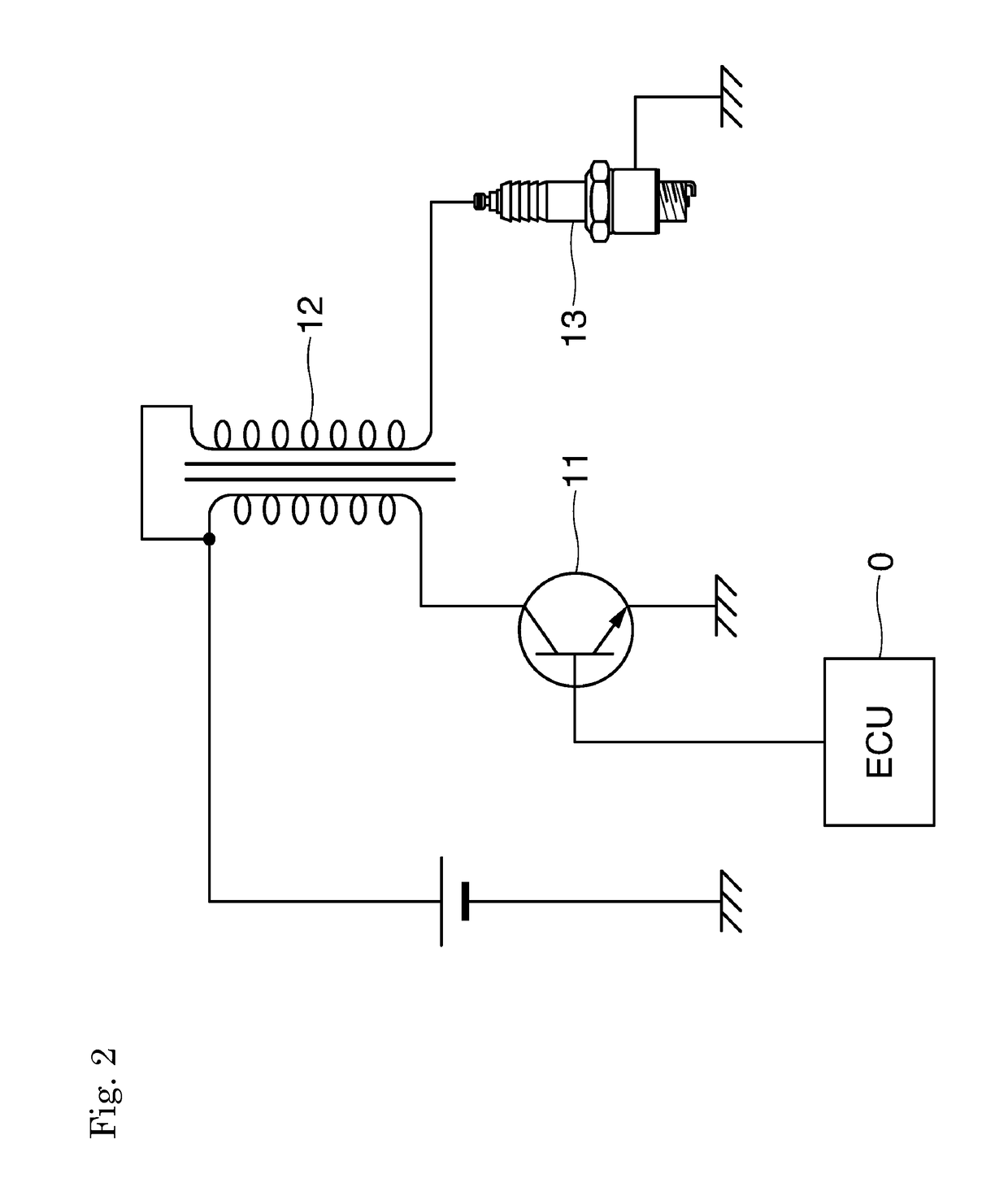
[0016]An ignition plug 13 is attached to a ceiling part of a combustion chamber of the cylinder 1. FIG. 2 shows an...


PUM


Abstract

To alleviate or eliminate a problem of unburned fuel discharged to the outside of a cylinder in a case in which an air fuel mixture is insufficiently combusted in a combustion chamber. During the expansion stroke in which a high voltage is applied to an ignition plug via an ignition coil, and a spark discharge is caused to occur at the ignition plug, thereby the air fuel mixture in the combustion chamber is ignited and combusted, in a case in which deterioration of combustion state is detected, a microwave electric field is created in the combustion chamber prior to an opening timing of an exhaust valve at an end stage of the expansion stroke, thereby plasma is generated and enlarged in the combustion chamber.

Description

TECHNICAL FIELD[0001]The present invention relates to a control device for controlling a spark ignition type internal combustion engine.BACKGROUND ART[0002]An ignition device mounted in a spark ignition type internal combustion engine causes a spark discharge and ignition to occur between a central electrode and a ground electrode of an ignition plug by applying a high voltage generated in an ignition coil when an igniter is turned off to the central electrode of the ignition plug.[0003]Recently, in order to attain a stable flame by ensuring ignition of an air fuel mixture present in a combustion chamber of a cylinder, there is an attempt to perform an “active ignition” method of emitting a high frequency wave outputted from a high frequency oscillator or a microwave outputted from an electric field generation circuit, i.e., a magnetron, into the combustion chamber (see, for example, Japanese Unexamined Patent Application, Publication No. 2011-159477 and Japanese Unexamined Patent A...

Claims


Application Information

Patent Timeline
Patent Type & Authority Patents(United States)
IPC IPC(8): F02P5/00H01T13/02F02P3/02F02P5/04F02P9/00F02P23/04F02M27/04F02M26/05F02B29/04F02P17/12F02D35/02F02P3/04F02M26/23
CPCF02P5/04F02M27/042F02P3/0407F02P9/007F02P23/045F02B29/0406F02D35/021F02P2017/125F02P3/0442F02M26/05F02M26/23
Inventor UCHIDA, KATSUMISHIMA, YUTAOI, HIROAKINAKAJIMA, AKIRASERIZAWA, TAKESHIIKEDA, YUJI
Owner DAIHATSU MOTOR CO LTD
Learn More