Furnace cooling by steam and air injection

a technology of air injection and furnace, which is applied in the direction of steam boiler components, water feed control, steam boiler components, etc., can solve the problems of uncooled parts of tubes, uncool parts of tubes, and steam bleed lowering the water level in the boiler circulation system, so as to reduce or avoid the effect of additional costs

Inactive Publication Date: 2018-06-05
THE BABCOCK & WILCOX CO
View PDF9 Cites 0 Cited by
  • Summary
  • Abstract
  • Description
  • Claims
  • Application Information

AI Technical Summary

Benefits of technology

[0009]The processes, systems and equipment described herein can protect power generation devices and their components against thermal damage due to abnormal operating conditions, while reducing or altogether avoiding the additional costs associated with providing steam drums with additional capacity and / or an independently powered boiler water pump.
[0011]In one aspect is provided a CFB boiler arrangement that includes a furnace, a solids separator system, a steam transporting circuit, and at least one secondary air inlet mechanism adapted to introduce into the CFB boiler furnace steam and air when needed (e.g., during abnormal operating conditions such as a black plant trip). The introduced stream of steam and air can accelerate cooling of solids separator system, which in turn can reduce or eliminate the cost of means necessary to prevent damage to uncooled boiler tubes, such as additional drum capacity and / or an independently powered boiler water pump.
[0013]The CFB boiler arrangement optionally can include a dribble pump connected to a steam drum in the steam circuit to maintain water flow to the steam drum, thereby offsetting steam lost from the steam circuit due to injection into the furnace.
[0015]Also provided is a method for cooling hot components of a boiler arrangement that includes a boiler enclosure defining a gas flow path for transporting flue gas during normal operation. The method finds particular utility in connection with boiler parts such as impact-type particle separator components, particularly during abnormal operation conditions such as a black plant trip. The method includes providing a source of steam and discharging a combined stream of the steam and ambient air into the gas flow path, thereby cooling the hot boiler components.
[0017]In yet another aspect of the present invention is a method for facilitating the cooling of components of a circulating fluidized bed boiler arrangement that comprises (1) a furnace with at least one primary air inlet and one or more secondary air inlets, wherein at least one of said one or more secondary air inlets is adapted to communicate with an air valve and encloses an eductor, (2) a solids separator system and (3) a steam / water circuit for circulating steam and water, said method comprising: a) conveying steam out of and away from said steam / water circuit to said eductor; and b) allowing said eductor to combine said steam with air introduced through said air valve, said air originating from a source external to said boiler arrangement; and c) introducing said combined stream into said furnace, thereby reducing the internal temperature of said furnace and helping to cool said components.
[0018]Steam itself, with a typical temperature range of ˜150° to ˜400° C. (300° to 750° F.), is substantially cooler than the temperature of uncooled boiler parts such as components of a solids separating unit, typically ˜750° to ˜925° C. (1400° to 1700° F.). Nevertheless, ambient air has a temperature that is substantially lower than that of steam. Thus, a combined discharge of steam and air into the furnace of a boiler significantly reduces the amount of time needed to cool boiler parts, e.g., solids separating unit components, to a temperature level considered safe in view of the materials of components (such as tubes) in the vicinity.

Problems solved by technology

Such steam bleed lowers the water level in the boiler circulation system, however.
If the water level recedes below the furnace roof, portions of the tubes become uncooled, and the residual heat of the uncooled parts of the solids separator can damage the uncooled tube portions.
Both of these increase boiler cost, however.
This solution can reduce the amount of the extra steam drum capacity, but it does not usually altogether eliminate the need for additional capacity nor for the independently powered boiler water pump.

Method used


Image

  • Furnace cooling by steam and air injection
  • Furnace cooling by steam and air injection
  • Furnace cooling by steam and air injection

Examples


Embodiment Construction

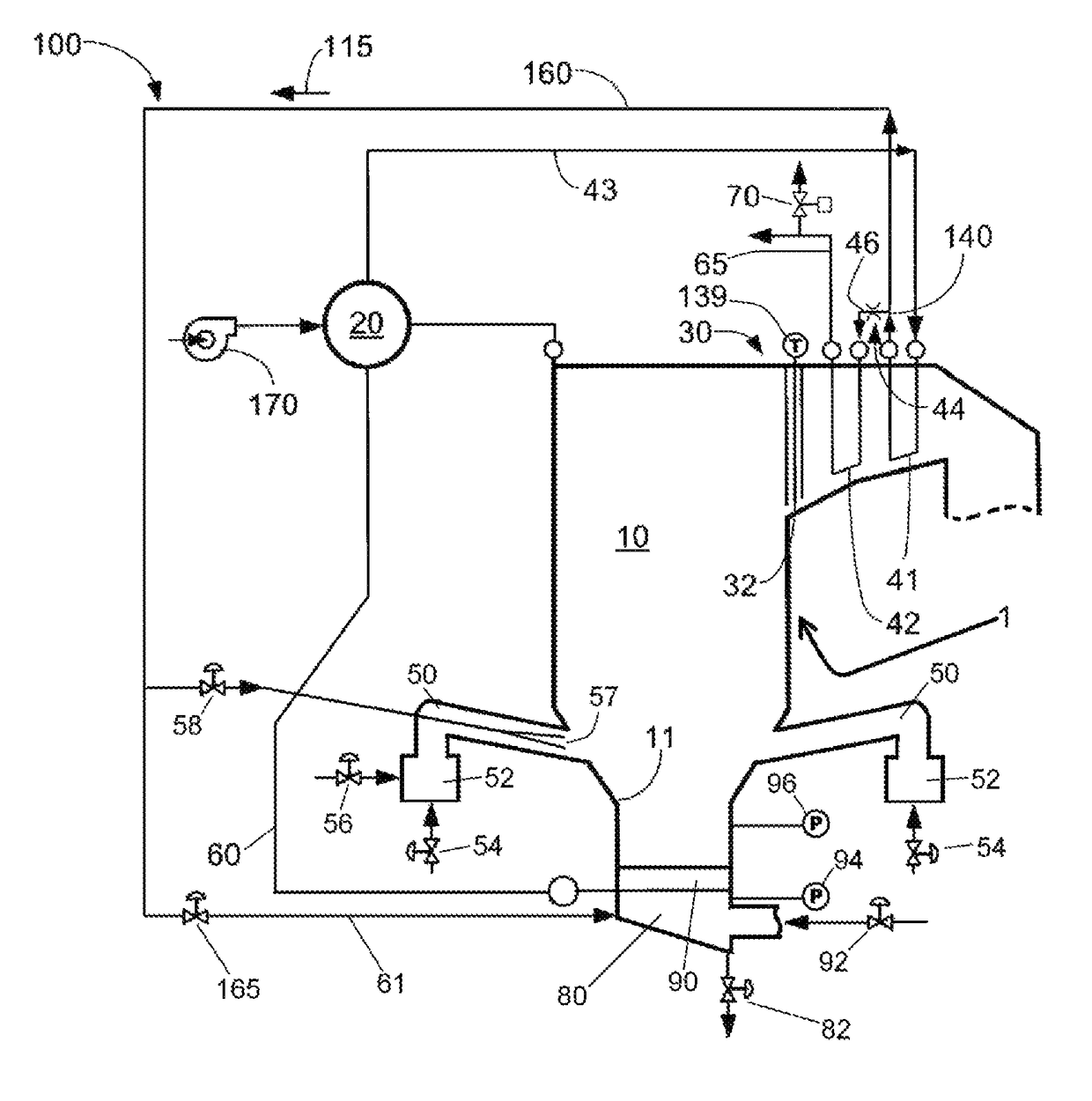
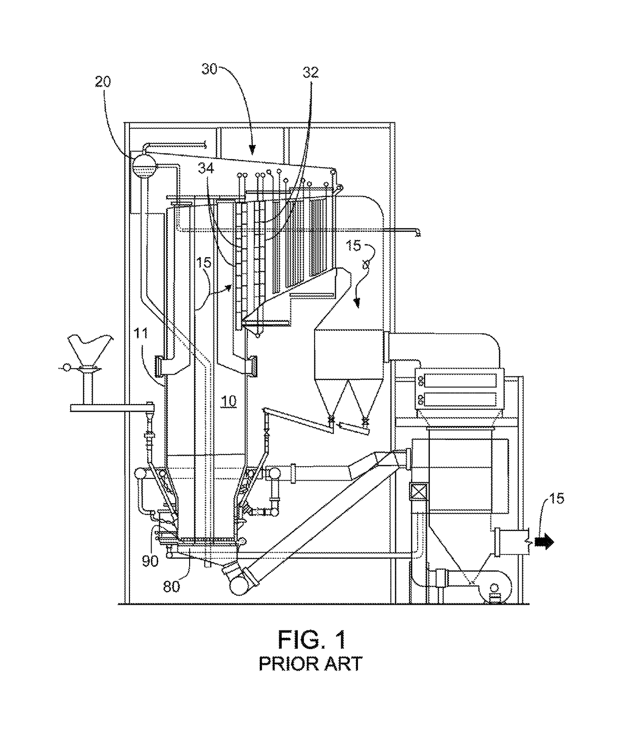
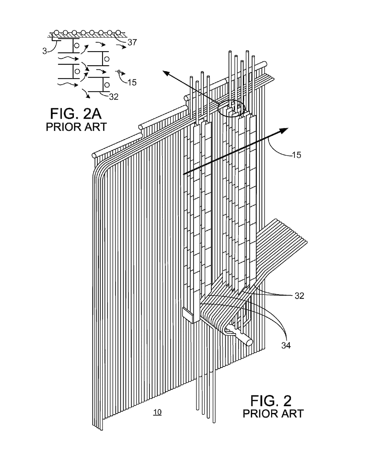
[0024]A more complete understanding of the components, processes, systems, methods and apparatuses disclosed herein can be obtained by reference to the accompanying drawings. The figures are merely schematic representations based on convenience and the ease of demonstrating the present disclosure, and is, therefore, not intended to indicate relative size and dimensions of the devices or components thereof and / or to define or limit the scope of the exemplary embodiments.

[0025]Although specific terms are used in the following description for the sake of clarity, these terms are intended to refer only to the particular structure of the embodiments selected for illustration in the drawings, and are not intended to define or limit the scope of the disclosure. In the drawings and the following description below, it is to be understood that like numeric designations refer to components of like function.

[0026]The singular forms “a,”“an,” and “the” include plural referents unless the context...


PUM


Abstract

A system can quickly cool and de-pressurize a boiler arrangement under non-normal operating conditions such as loss of plant power. A discharge system injects into the furnace a combined stream of steam from a steam discharge system and ambient air, thereby both cooling components of the boiler arrangement and reducing pressure in the steam / water circuit. This reduces or eliminates the additional cost associated with providing extra capacity in a steam drum and / or an independently powered boiler water pump. The system is particularly useful for quickly cooling the U-beams of a circulating fluidized bed boiler during a black plant condition.

Description

BACKGROUND INFORMATION[0001]Circulating fluidized bed (CFB) boilers are used in the production of steam for industrial processes and electric power generation; see, for example, U.S. Pat. Nos. 5,799,593, 4,992,085, 4,891,052, 5,343,830, 5,378,253, 5,435,820, and 5,809,940. For an overview of the design and operation of CFB boilers, see Steam: Its Generation and Use, 41st ed., Chapter 17 (2005; The Babcock & Wilcox Company, Barberton, Ohio) and Steam: Its Generation and Use, 42nd ed., Chapter 17 (2015; The Babcock & Wilcox Company, Barberton, Ohio).[0002]In a CFB boiler, upward gas flow carries reacting and non-reacting solids to an outlet at the upper portion of the furnace where the solids are separated from the gas, typically by a staggered array of impact-type particle separators. The gaseous components of the stream navigate around the separator unit, while the entrained solids deflect and return to the furnace bottom. Impact-type particle separators, which generally are not coo...

Claims


Application Information

Patent Timeline
Patent Type & Authority Patents(United States)
IPC IPC(8): F22B37/44F22D5/26F22D11/00
CPCF22D11/003F22D5/26F22B37/44F22B31/0061
Inventor MARYAMCHIK, MIKHAILSZMANIA, MICHAEL JWIETZKE, DONALD L
Owner THE BABCOCK & WILCOX CO
Why Eureka
Try Eureka