
Methods for on-line, high-accuracy estimation of battery state of power

a battery state and high accuracy technology, applied in the field of real-time characterization of electrochemical systems, can solve the problems of difficult on-line characterization of batteries or fuel cells in vehicles, difficult prediction of sop, general non-applicability of on-line applications, etc., and achieve the effect of improving the stability of the method

Active Publication Date: 2018-06-05
HRL LAB
View PDF14 Cites 21 Cited by
  • Summary
  • Abstract
  • Description
  • Claims
  • Application Information

AI Technical Summary

Benefits of technology

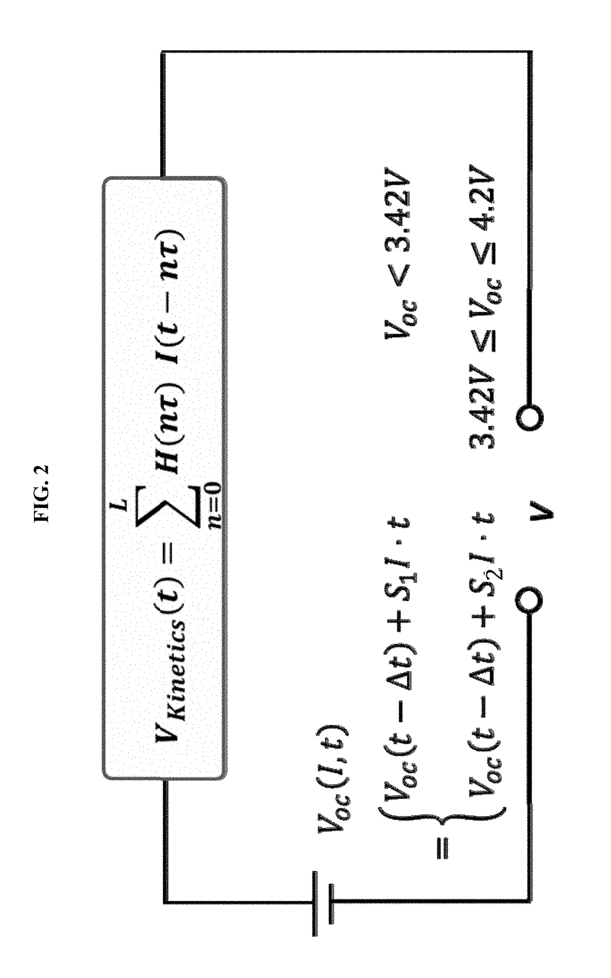
The patent describes a method for filtering data in a battery. The method uses a finite-impulse-response filter and an extended Kalman filter. The number of parameters used in the filter can be adjusted to improve stability or to accommodate battery kinetics. The technical effect of this method is a more accurate and reliable battery management system.

Problems solved by technology

On-line characterization of batteries or fuel cells in vehicles is difficult, due to very rough noisy environments.
It is challenging to predict the SOP, because the battery behavior is nonlinear when it is operated at its peak power.
Traditional methods, such as hybrid pulse power characterization, have been used in the lab for SOP prediction but are generally not applicable for on-line applications due to the requirement for specific driving profiles.
However, there are obvious drawbacks with these static limits.
First of all, these limits don't reflect battery aging.
Those boundaries for safe operation may need to be updated since they are may not be safe as a battery becomes old.
Secondly, these limits tend to be conservative during the beginning life of battery because they were determined to accommodate many non-predictable factors.

Method used


Image

  • Methods for on-line, high-accuracy estimation of battery state of power
  • Methods for on-line, high-accuracy estimation of battery state of power
  • Methods for on-line, high-accuracy estimation of battery state of power

Examples


examples

[0155]The battery used in these Examples is a single-cell lithium-ion battery which has a nominal capacity of 5.0 Ah and a voltage range of 2.7 to 4.1 V. A software program coded with MATLAB® is written to carry out calculations. The method is implemented and integrated with a Hardware-in-the-Loop (HWIL) battery testing system. The main facilities include a single-channel tester (BT2000, Arbin Instruments, College Station, Tex., US) that provides up to 5 kW at potentials between 0.6 V and 5 V±1 mV and current ranges up to 1 kA±10 mA, and a thermal control chamber (Test Equity, Moorpark, Calif., US) for accommodating the lithium-ion battery with a programmable range from −40° C. to 130° C. (±10° C.) in a thermal chamber. A PC computer communicates with the tester to initiate the specific driving profiles, and to receive the I-V-T response measured from the battery. The communications between the above-mentioned modules are realized with TCP / IP protocols. The temporal jitter of the re...


PUM


Abstract

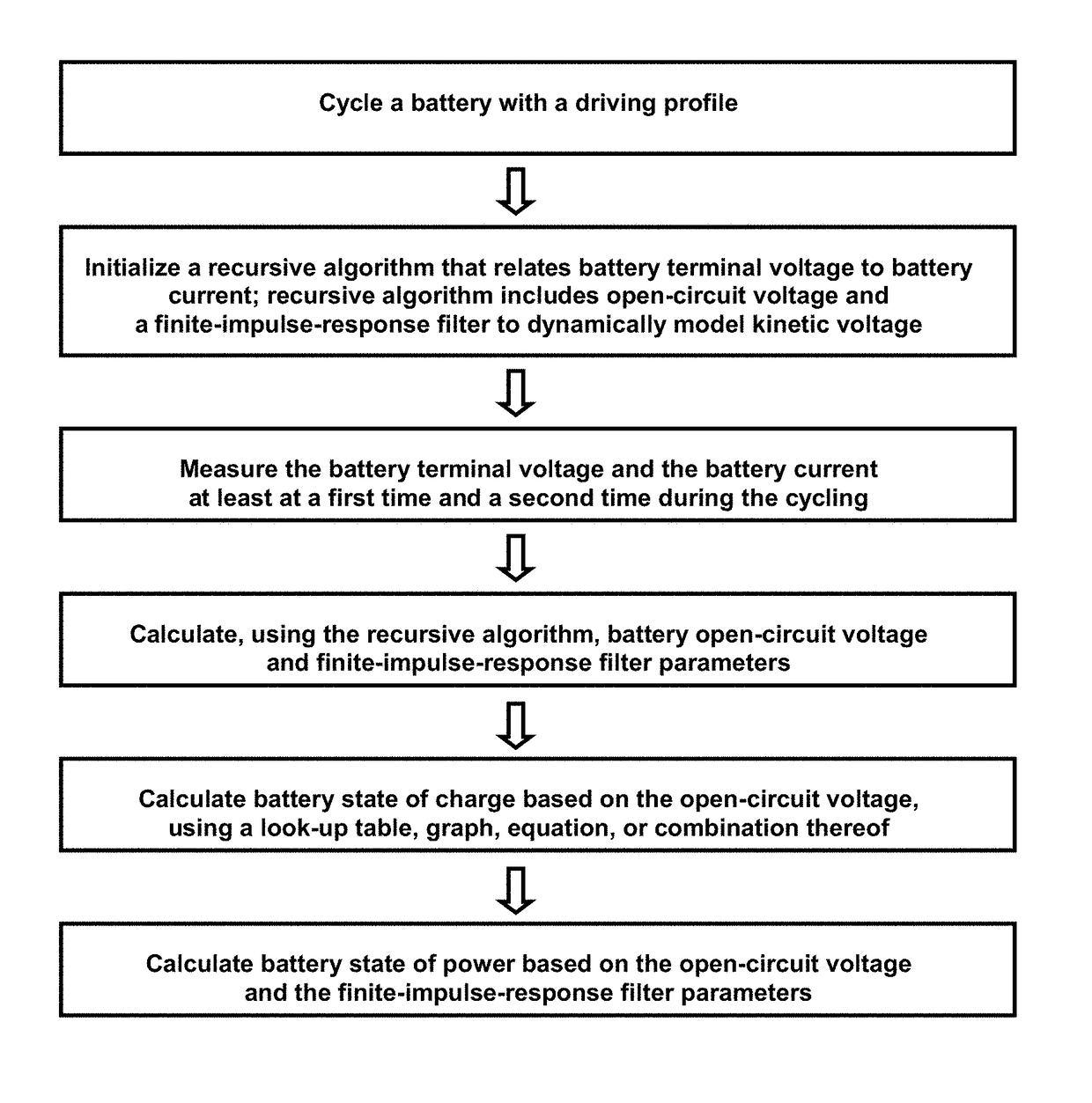
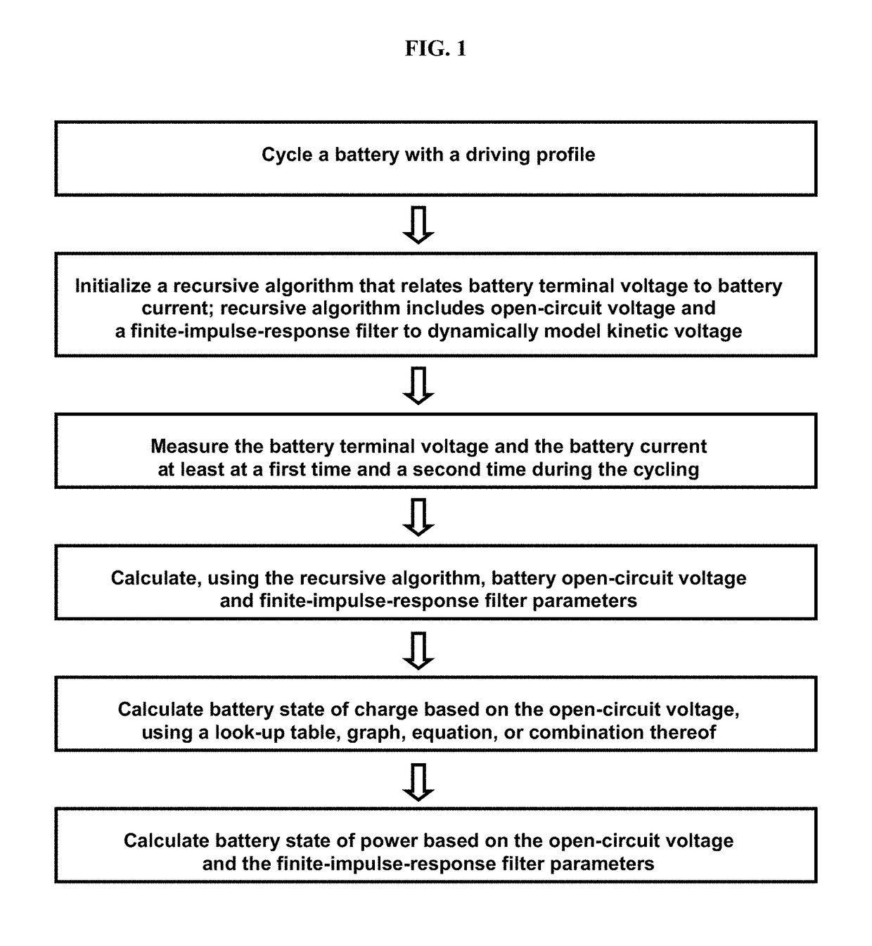
Some variations provide a method for real-time estimation of state of charge and state of power of a battery, comprising: (a) cycling a battery with a driving profile; (b) utilizing a recursive algorithm that relates battery terminal voltage to battery current, wherein the algorithm includes open-circuit voltage and a finite-impulse-response filter to dynamically model kinetic voltage; measuring the battery terminal voltage and the battery current at least at a first time and a second time during cycling; calculating battery open-circuit voltage and finite-impulse-response filter parameters; calculating battery state of charge based on the open-circuit voltage; and calculating battery state of power based on the open-circuit voltage and the finite-impulse-response filter parameters. An extended Kalman filtering technique is incorporated for real-time updating of FIR model parameters. Only a single FIR filter is necessary, making these methods applicable for battery-powered systems with limited computing and storage capabilities.

Description

PRIORITY DATA[0001]This non-provisional patent application claims priority to U.S. Provisional Patent Application No. 61 / 922,278, filed Dec. 31, 2013, which is hereby incorporated by reference herein in its entirety.FIELD OF THE INVENTION[0002]The present invention generally relates to the real-time characterization of electrochemical systems, such as batteries and fuel cells.BACKGROUND OF THE INVENTION[0003]An electrochemical system either derives electrical energy from chemical reactions, or facilitates chemical reactions through the introduction of electrical energy. An electrochemical system generally includes a cathode, an anode, and an electrolyte, and is typically complex with multiple heterogeneous subsystems, multiple scales from nanometers to meters. On-line characterization of batteries or fuel cells in vehicles is difficult, due to very rough noisy environments.[0004]In many battery-powered systems such as electric vehicles, laptops, and smartphones, accurate estimation ...

Claims


Application Information

Patent Timeline
IPC IPC(8): G01R31/36
CPCG01R31/3648G01R31/3606G01R31/387G01R31/382
Inventor WANG, SHUOQINVU, LUAN D.JIANG, QIN
Owner HRL LAB
Learn More