
High dynamic range detector correction algorithm

a detector correction and high dynamic range technology, applied in the direction of instruments, x/gamma/cosmic radiation measurement, particle separator tube details, etc., can solve the problems of high dynamic range detection system, non-paralyzing electronics, and detectors that cannot supply current quickly,

Active Publication Date: 2018-06-05
DH TECH DEVMENT PTE
View PDF10 Cites 4 Cited by
  • Summary
  • Abstract
  • Description
  • Claims
  • Application Information

AI Technical Summary

Benefits of technology

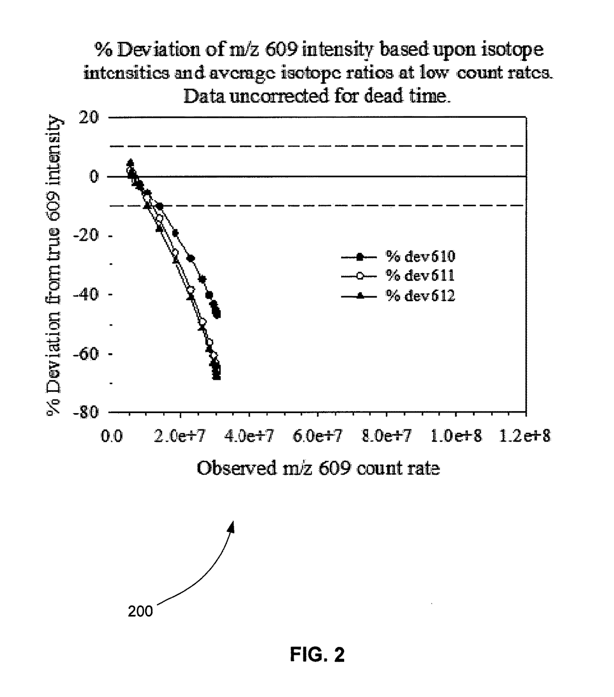
The patent text describes an ion detection system in a quadrupole mass spectrometer and the various methods for measuring the output of the detector. The technical effects of the patent text include the correction of dead time losses in the non-paralyzable high dynamic range detection system and the need for methods to address the issue of dead time extensions in the non-paralyzable system. The patent text also describes a computer system and various methods for calculating the true count rate of ions based upon the second, third, and fourth isotopes of reserpine.

Problems solved by technology

Saturation occurs when the detector cannot supply current quickly enough to produce an output pulse after receiving a number of ions at the input.
At high count rates, however, a high dynamic range detection system, employing non-paralyzing electronics, can also exhibit dead time extensions which are the result of a characteristic of the non-paralyzing electronics.

Method used


Image

  • High dynamic range detector correction algorithm
  • High dynamic range detector correction algorithm
  • High dynamic range detector correction algorithm

Examples


Embodiment Construction

[0021]Computer-Implemented System

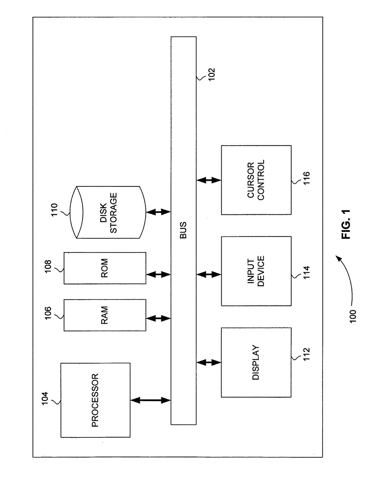
[0022]FIG. 1 is a block diagram that illustrates a computer system 100, upon which embodiments of the present teachings may be implemented. Computer system 100 includes a bus 102 or other communication mechanism for communicating information, and a processor 104 coupled with bus 102 for processing information. Computer system 100 also includes a memory 106, which can be a random access memory (RAM) or other dynamic storage device, coupled to bus 102 for storing instructions to be executed by processor 104. Memory 106 also may be used for storing temporary variables or other intermediate information during execution of instructions to be executed by processor 104. Computer system 100 further includes a read only memory (ROM) 108 or other static storage device coupled to bus 102 for storing static information and instructions for processor 104. A storage device 110, such as a magnetic disk or optical disk, is provided and coupled to bus 102 for storing...


PUM


Abstract

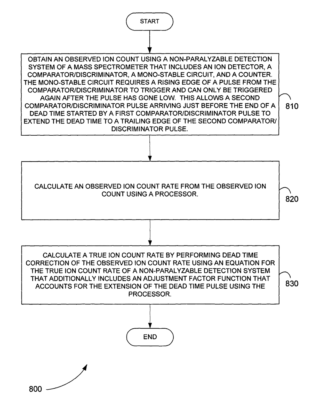
Systems and methods are provided to perform dead time correction. An observed ion count rate is obtained using a non-paralyzable detection system of a mass spectrometer. The detection system includes an ion detector, a comparator / discriminator, a mono-stable circuit and a counter. The non-paralyzable detection system exhibits dead time extension at high count rates. The extension of the dead time occurs because the mono-stable circuit requires a rising edge to trigger and can only be triggered again after the output pulse from the comparator / discriminator has gone low. This allows a second comparator / discriminator pulse arriving just before the end of the dead time started by a first comparator / discriminator pulse to extend the dead time to the trailing edge of the second comparator / discriminator pulse. A true ion count rate is calculated by performing dead time correction of the observed ion count rate.

Description

CROSS REFERENCE TO RELATED APPLICATION[0001]This application claims the benefit of U.S. Provisional Patent Application Ser. No. 61 / 648,653, filed May 18, 2012, the content of which is incorporated by reference herein in its entirety.INTRODUCTION[0002]An ion detection system in a quadrupole mass spectrometer is made up of an ion detector, a current to voltage pre-amplifier, a comparator / discriminator, a mono-stable circuit, and a counter. The ion detector generates a current pulse for every ion that strikes it; these current pulses are passed to the current to voltage pre-amplifier where they are converted into voltage pulses. The voltage pulses are passed to a comparator / discriminator which generates a logic pulse when the leading edge of the voltage pulse exceeds the discriminator threshold. The logic pulse ends when the trailing edge of the voltage pulse drops below the discriminator threshold level. The comparator / discriminator removes noise by only transmitting voltage pulses th...

Claims


Application Information

Patent Timeline
Patent Type & Authority Patents(United States)
IPC IPC(8): H01J49/00H01J49/02G01T1/17
CPCH01J49/0027H01J49/0009H01J49/025H01J49/0036G01T1/171
Inventor COLLINGS, BRUCE ANDREWDIMA, MARTIANIVOSEV, GORDANA
Owner DH TECH DEVMENT PTE
Learn More