Method of manufacturing a circuit breaker and method of manufacturing a battery pack including the circuit breaker

a technology of circuit breakers and manufacturing methods, which is applied in the field of circuit breakers to achieve the effects of reducing the amount of temperature lowering, reducing the number of circuit breakers rejected at the anneal step, and small reset temperature difference in the fabricated circuit breakers

Active Publication Date: 2018-06-12
OTSUKA TECH CORP
View PDF17 Cites 0 Cited by
  • Summary
  • Abstract
  • Description
  • Claims
  • Application Information

AI Technical Summary

Benefits of technology

[0017]The circuit breaker fabricated by the method described above has the characteristic that variation can be reduced in the temperature for reset to the ON-state after exposure to a heating environment such as the solder reflow process. This is because the fabrication method does not heat-treat the bimetallic strip alone as in related-art methods. Instead, the circuit breaker assembly, which houses the bimetallic strip and moving contact metal plate, is heated as an assembled unit in an anneal oven and subsequently cooled to anneal both the bimetallic strip and moving contact metal plate in the anneal step. The moving contact metal plate annealed in the assembled state becomes more robust (stronger) after anneal and cooling, can reduce the size of the temperature distribution for reset to the ON-state, and can make the amount of reset temperature reduction smaller. Accordingly, for circuit breakers fabricated as described above, there are essentially no circuit breakers with reset temperature shift greater than or equal to 10° C. after a solder reflow process step that heats the circuit breakers with a maximum temperature from 240° C. to 260° C. for a maximum of 10 sec. In contrast, approximately 50% of un-annealed (related-art) circuit breakers have reset temperature shift greater than or equal to 10° C. after the solder reflow process.
[0037]The method of manufacturing a battery pack of the present invention can set the anneal temperature for heating the circuit breaker assembly 70 in the anneal oven 80 during the anneal step to a value lower than the temperature of the solder reflow oven 85. In this case, quenching stress relief, as well as prevention of shift with aging and improved abrasion resistance can be realized.

Problems solved by technology

This is because the fabrication method does not heat-treat the bimetallic strip alone as in related-art methods.

Method used


Image

  • Method of manufacturing a circuit breaker and method of manufacturing a battery pack including the circuit breaker
  • Method of manufacturing a circuit breaker and method of manufacturing a battery pack including the circuit breaker
  • Method of manufacturing a circuit breaker and method of manufacturing a battery pack including the circuit breaker

Examples


first embodiment

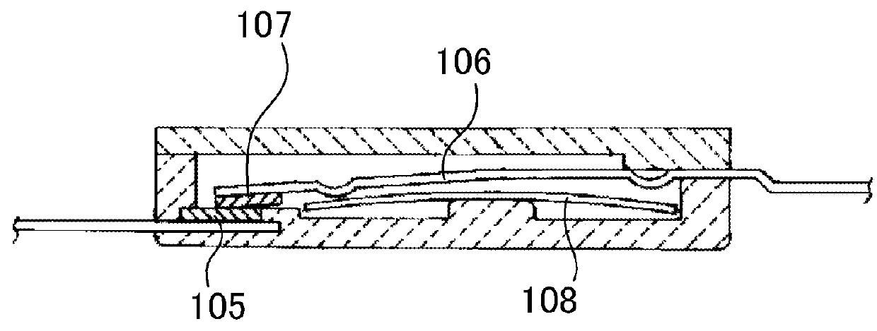
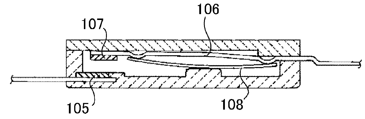
[0106]A circuit breaker assembly 70 having the structure shown in FIGS. 4-9 was fabricated with a moving contact metal plate 6 using a Cu—Ni—Si system alloy including Mg and Cr. In the anneal step, the circuit breaker assembly 70 was introduced into the heating tunnel 81 of the anneal oven 80 shown in FIG. 20, heated with an oven center region temperature of 230° C. over a 30 sec heating tunnel 81 transit time, subsequently discharged from the heating tunnel 81 via the conveyor belt 82, and cooled to complete the anneal and produce a heat-treated circuit breaker 71. The Cu—Ni—Si system alloy including Mg and Cr used in this first embodiment had the following composition.

Cu 96.15 mass %

Ni 2.3 mass %

Si 0.65 mass %

Sn 0.15 mass %

Zn 0.5 mass %

Mg 0.1 mass %

Cr 0.15 mass %

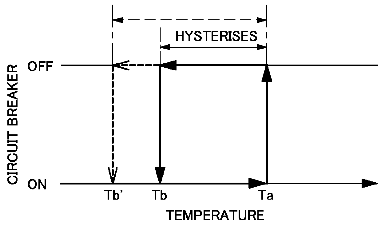
[0107]Ten circuit breakers fabricated by the method of the first embodiment had little reduction in reset temperature after the solder reflow step, and reset temperature showed little inconsistency as well. Measurements we...


PUM

PropertyMeasurementUnit
temperatureaaaaaaaaaa
reset temperatureaaaaaaaaaa

Abstract

The circuit breaker is fabricated by an assembly step that makes a circuit breaker assembly with a moving contact metal plate, stationary contact metal plate, and bimetallic strip disposed in prescribed locations in an external case; and an anneal step that introduces the circuit breaker assembly made in the assembly step into an anneal oven, heats the circuit breaker assembly in the anneal oven and then cools it to anneal both the moving contact metal plate and the bimetallic strip and produce a heat-treated circuit breaker.

Description

BACKGROUND OF THE INVENTION[0001]1. Field of the Invention[0002]The present invention relates to a circuit breaker primarily housed in electrical equipment such as a battery pack to cut-off current flow when temperature becomes greater than a preset value.[0003]2. Description of the Related Art[0004]The safety level of battery packs and apparatus such as electric motors can be improved by cutting-off current flow in abnormally high-temperature conditions. This can be implemented by using a circuit breaker that disconnects (switches OFF) contact connection at a set temperature. For example, since abnormal charging and discharging of a battery pack housing lithium ion batteries can result in battery heating, a circuit breaker is included as a protection device to cut-off current flow at high-temperature allowing the battery pack to be used safely. In addition, since temperature can become abnormally high when a device such as a motor is overloaded and / or passes excessive current, that...

Claims


Application Information

Patent Timeline
Patent Type & Authority Patents(United States)
IPC IPC(8): H01H11/00H01L23/00H01H83/22H01H71/16H01H71/02H01H65/00H05K3/34H01H71/00H01M50/284H01M50/574
CPCH01H71/0207H01H71/16H01H83/223H05K3/34H01L24/26Y10T29/49105H01H2071/004H05K3/3426H05K3/3494H01M2200/101H01H37/5436Y02E60/10H01M50/284H01M50/574H01H11/04
Inventor NAKANISHI, YOSHIHIROSHIBUYA, SHIROTANABE, KAZUO
Owner OTSUKA TECH CORP
Why Eureka
Try Eureka