Low loss synchronous rectifier for application to clamped-mode power converters

a synchronous rectifier and clamped-mode technology, applied in the direction of pulse manipulation, pulse technique, instruments, etc., can solve the problems of limited efficiency, inefficiency of synchronous rectifiers, and limited use of synchronous rectifiers, and achieve the effect of improving the efficiency of rectifiers

Inactive Publication Date: 2000-02-15
LINEAGE POWER +1
View PDF35 Cites 35 Cited by
  • Summary
  • Abstract
  • Description
  • Claims
  • Application Information

AI Technical Summary

Benefits of technology

A synchronous rectifiers is combined with a clamped-mode buck derived power converter. In one illustrative embodiment a hybrid rectifier includes a MOSFET rectifying device active in a first cyclic interval of the conduction/nonconduction sequence of the power switch. A second rectifying device embodied in one illustrative embodiment as a low forward voltage drop bipolar

Problems solved by technology

Use of synchronous rectifiers has been limited however by the inefficiency of these rectifiers in buck derived converter topologies.
Efficiency is limited due to the nature of switching of buck derived converters (i.e buck, buck-boost, boost converters including forward a

Method used


Image

  • Low loss synchronous rectifier for application to clamped-mode power converters
  • Low loss synchronous rectifier for application to clamped-mode power converters
  • Low loss synchronous rectifier for application to clamped-mode power converters

Examples


Embodiment Construction

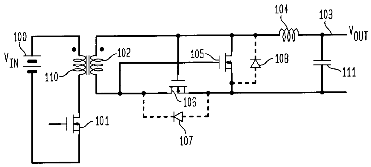
In the converter shown in the FIG. 1, a conventional forward topology of the prior art with an isolating power transformer is combined with a self synchronized synchronous rectifier. In such a rectifier controlled devices are used with the control terminals being driven by an output winding of the power transformer.

A DC voltage input V.sub.in, at input 100, is connected to the primary winding 110 of the power transformer by a MOSFET power switch 101. The secondary winding 102 is connected to an output lead 103 through an output filter inductor 104 and a synchronous rectifier including the MOSFET rectifying devices 105 and 106. Each rectifying device includes a body diode 108 and 107, respectively.

With the power switch 101 conducting, the input voltage is applied across the primary winding 110. The secondary winding 102 is oriented in polarity to respond to the primary voltage with a current flow through the inductor 104, the load connected to output lead 103 and back through the MOS...


PUM


Abstract

A synchronous rectifier for use with a clamped-mode power converter uses in one embodiment a hybrid rectifier with a MOSFET rectifying device active in one first cyclic internal of the conduction/nonconduction sequence of the power switch and a second rectifying device embodied in one illustrative embodiment as a low voltage bipolar diode rectifying device active during an alternative interval to the first conduction/nonconduction interval. The gate drive to the MOSFET device is continuous at a constant level for substantially all of the second interval which enhances efficiency of the rectifier. The bipolar rectifier device may also be embodied as a MOSFET device. The subject rectifier may be used in both forward and flyback power converters.

Description

FIELD OF THE INVENTIONThis invention relates to switching type power converters and in particular to forward and flyback converters having a clamp-mode topology.BACKGROUND OF THE INVENTIONSelf synchronized rectifiers refer to rectifiers using MOSFET rectifying devices having control terminals which are driven by voltages of the windings of the power transformer in order to provide the rectification of the output of the transformer. Use of synchronous rectifiers has been limited however by the inefficiency of these rectifiers in buck derived converter topologies. Efficiency is limited due to the nature of switching of buck derived converters (i.e buck, buck-boost, boost converters including forward and flyback topologies) and due to the variability of the transformer reset voltages in the forward type converters. This variability of reset voltage limits the conduction time of one of the MOSFET rectifiers, diminishing the effectiveness and efficiency of the rectifier. This is because ...

Claims


Application Information

Patent Timeline
IPC IPC(8): H02M3/335H02M3/24H02M3/28H02M7/217
CPCH02M3/33569H02M3/33592H02M7/217Y02B70/1475Y02B70/10
Inventor ROZMAN, ALLEN FRANK
Owner LINEAGE POWER
Why Eureka
Try Eureka