Device and method for the surgical anastomasis of tubular structures

a tubular structure and anastomosis technology, applied in the field of tubular structure surgical anastomosis, can solve the problems of increasing the likelihood of thrombosis and/or structural failure, increasing the difficulty of surgical anastomosis, and reducing the surgical anastomosis, so as to reduce tissue trauma, less technical demands, and the effect of reducing the problem

Inactive Publication Date: 2001-03-20
SURGICAL INNOVATIONS
View PDF4 Cites 13 Cited by
  • Summary
  • Abstract
  • Description
  • Claims
  • Application Information

AI Technical Summary

Benefits of technology

An object of the present invention is to provide a device and method for surgically joining severed small tubular structures that minimizes the problems associated with methods of the prior art. It renders the process less technical

Problems solved by technology

However, considerable surgical dexterity is required.
Such trauma increases the likelihood of thrombosis and/or structural failure.
(a) Loss of configuration. When tubular structures, such as blood vessels, are emptied of their pressurized contents (such as blood), the tubular lumen collapses and the tubular shape is lost. The ends of such severed, collapsed structures are difficult to visualize in their previously intact configuration or their preferably restored configuration. They are also difficult to grasp and manipulate in order to suture.
(b) Trauma from instrumentation. In placing sutures through the vessel wall, the suture needle is passed through the wall either from outside to in or from inside to out. To facilitate passing a suture needle inward towards the lumen, an instrument, such as a small forceps, is typically inserted into the lumen in order to provide counter pressure to the thrust of the suturing needle, as well as to attempt to separate the wall being sutured from the wall behind it. Alternatively, the surgeon may be required to grasp the full thickness of the wall being sutured with a forceps in order to position it so that it may be pierced by the suturing needle. This requirement for forceps to grasp and manipulate the dissociated st

Method used


Image

  • Device and method for the surgical anastomasis of tubular structures
  • Device and method for the surgical anastomasis of tubular structures
  • Device and method for the surgical anastomasis of tubular structures

Examples


Embodiment Construction

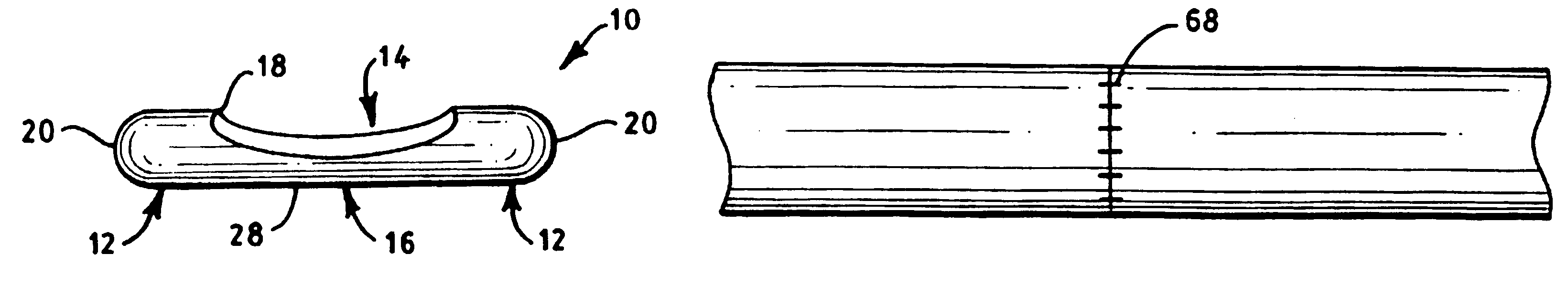
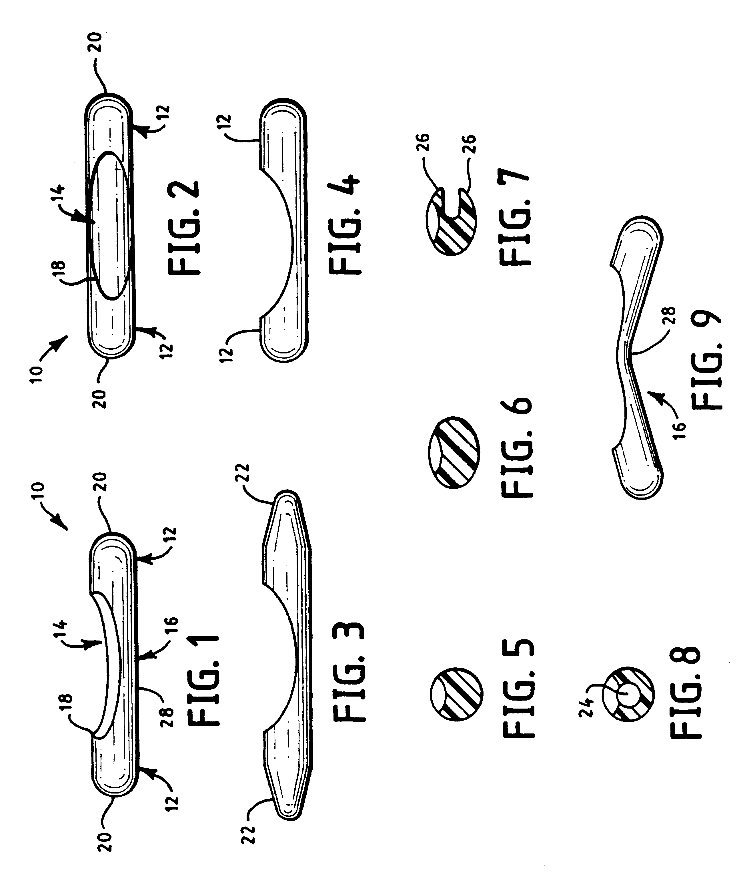
The basic embodiment 10 of the device of the present invention is illustrated in FIGS. 1 and 2. The basic device 10 has a generally cylindrical shape. The components of the basic device 10 include a pair of insertion arms 12 and a central depression 14. The depression 14 leaves a bridge 16 connecting the arms 12.

The insertion arms 12 are designed to be non-traumatic when in contact with the inside of the tubular structure. This is accomplished by either making the outer surface of the arms 12 smooth, by forming the arms 12 of a material that retains moisture, and / or by coating the arms 12 with a lubricant. As an aid to insertion, the free extremities 20 of the arms 12 are convexly rounded. Optionally, the free extremities are tapered, as at 22 in FIG. 3. A tapered extremity is easier to insert because the tubular structure, which is collapsed when empty, does not have to be opened as far to start the insertion process.

The arms 12 may have the same or different lengths, as in FIG. 4,...


PUM


Abstract

A device for assisting in anastomosis of tubular structures. The basic device has a generally cylindrical shape with a pair of insertion arms and a central depression that provides a space for the needle to move through within the tubular structures while simultaneously providing support so that the suture needle thrust does not collapse the tubular structure wall. The depression may be configured to guide the path of the needle. A bridge connects the arms and prevents the needle from inadvertently coming in contact with the wall opposite that of the wall being sutured. The method includes an initial suture to join the sutures, inserting the device into the openings of the two structures, placing sutures in the walls adjacent to the depression, optionally rotating the device so the depression is aligned with each suture as it is being placed, removing the device, and tightening the sutures to complete the anastomosis.

Description

BACKGROUND OF THE INVENTION1. Field of the InventionThe present invention relates to a device and method for surgically joining severed small tubular structures.2. The Prior ArtIt is presently possible to surgically join small tubular structures, for example, severed arteries smaller than 5.0 millimeters (mm) in size, and even less than 1.0 mm in size. However, considerable surgical dexterity is required. If reunification of a patent conduit with normal or nearly normal flow is to be achieved, great pains must be taken to insure gentle handling of delicate tissues, particularly avoiding unnecessary stretching, crushing, or piercing of the tissues. Such trauma increases the likelihood of thrombosis and / or structural failure.Anastomosis of small tubular structures is preferably performed under a microscope to aid in visualization. In the case of end-to-end anastomosis, the severed vessels are gently clamped so as to interrupt flow and to make the ends available for suture. An initial ...

Claims


Application Information

Patent Timeline
IPC IPC(8): A61B17/11A61B17/03A61B17/04A61B17/115
CPCA61B17/0482A61B17/11A61B2017/1135
Inventor WELLS-ROTH, DAVID
Owner SURGICAL INNOVATIONS
Why Eureka
Try Eureka