
Skewless differential switch and DAC employing the same

a differential switch and skewless technology, applied in the field of differential switches, can solve the problems of nyquist bandwidth, nyquist signal, nyquist signal, noise, etc., and achieve the effects of reducing the complexity of the clock generation circuitry of the switch controller, reducing the occurrence and duration of undesirable switch outputs, and reducing spurious switching

Inactive Publication Date: 2002-04-02
ANALOG DEVICES INC
View PDF3 Cites 36 Cited by
  • Summary
  • Abstract
  • Description
  • Claims
  • Application Information

AI Technical Summary

Benefits of technology

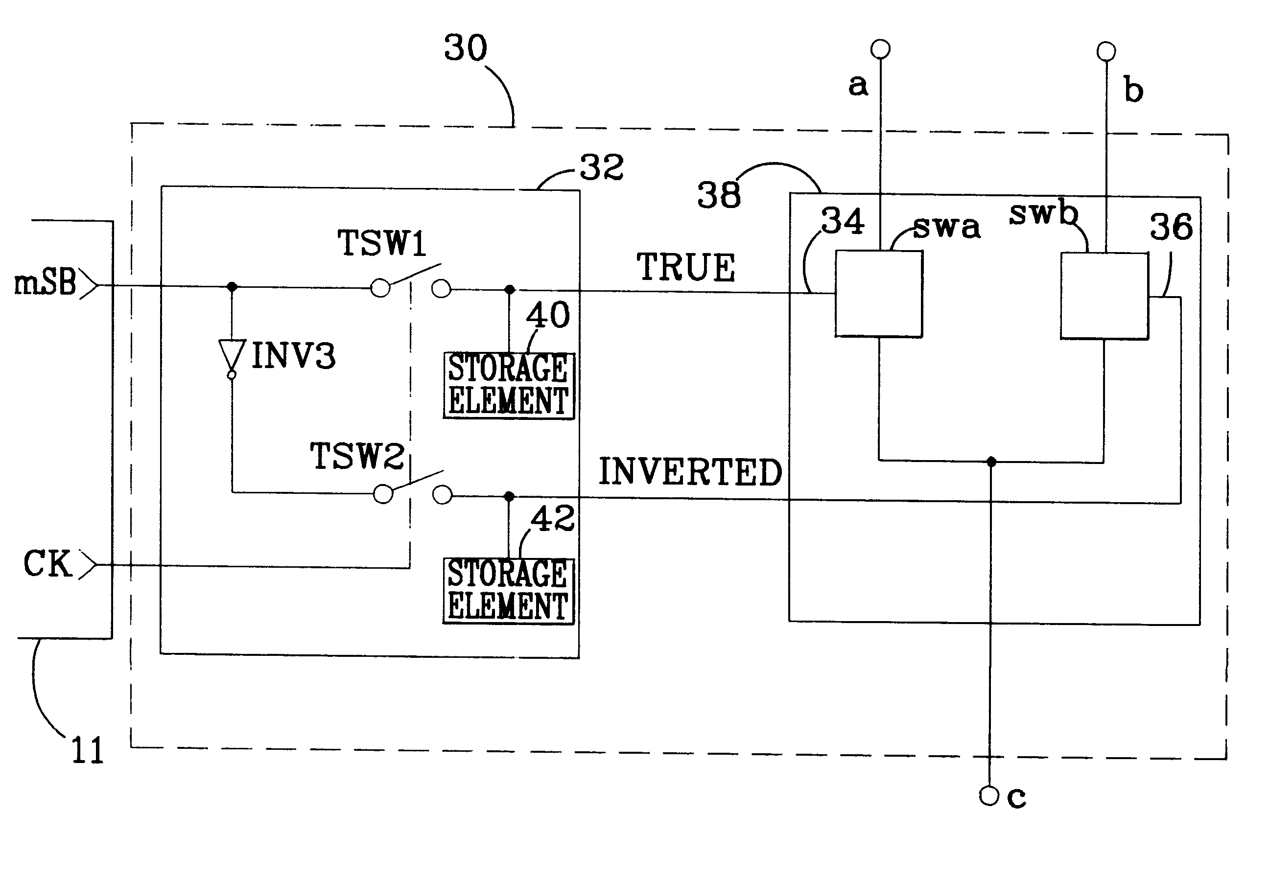
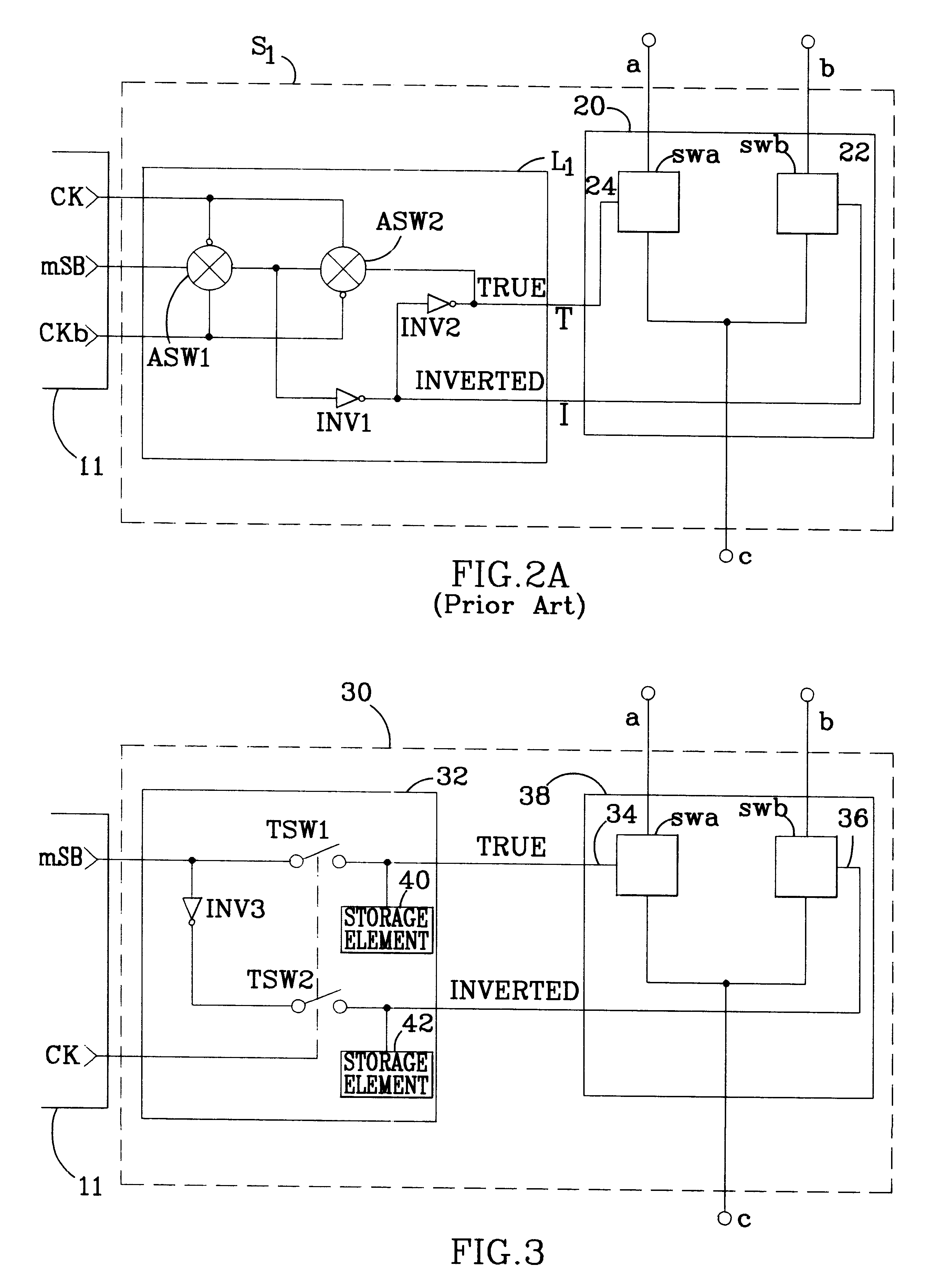
The invention is directed to a differential switch that minimizes the complexity of a switch controller's clock generation circuitry and reduces spurious switching, thereby reducing the occurrence and duration of undesirable switch outputs, or glitches. These goals are achieved by a latched differential switch which inverts the control input and then simultaneously transfers the control input and its complement through transfer switches into storage elements. Although inverting the control signal introduces a delay between the control signal and its complement (referred to as the "TRUE" and "INVERTED" signals hereinafter), simultaneously transferring them into storage elements eliminates this skew. The storage elements' outputs are connected to the control inputs of a differential switch pair, thus providing "de-skewed" control for a differential switch pair from a single binary control input.
In one implementation, the novel switch includes a n intermediate set of transfer switches, operated from the same "enable" signal as the first set of transfer switches, and an intermediate set of storage elements. The intermediate sets of switches and storage elements are interposed between the TRUE and INVERTED inputs and the first set of transfer switches. During the first cycle of the enable signal, the TRUE and INVERTED signals are simultaneously transferred into the intermediate set of storage elements. As described above, this simultaneous transfer eliminates the skew between the TRUE and INVERTED signals. The TRUE and INVERTED signals are then transferred into the first storage element, which is isolated from the intermediate storage element, during the second cycle of the enable signal.
The isolation between the first and second storage elements prevents transitions at the input to the second storage element from appearing at the first storage element. The TRUE and INVERTED signals are therefore available from the second storage element without the skew between them that had been introduced by inverting the control signal. The outputs of the first storage element are connected, as described above, to the control inputs of a differential switch pair, thus providing "de-skewed" control for the switch pair. The novel switch may be used, for example, within a DAC to reduce the DAC's glitch energy output.

Problems solved by technology

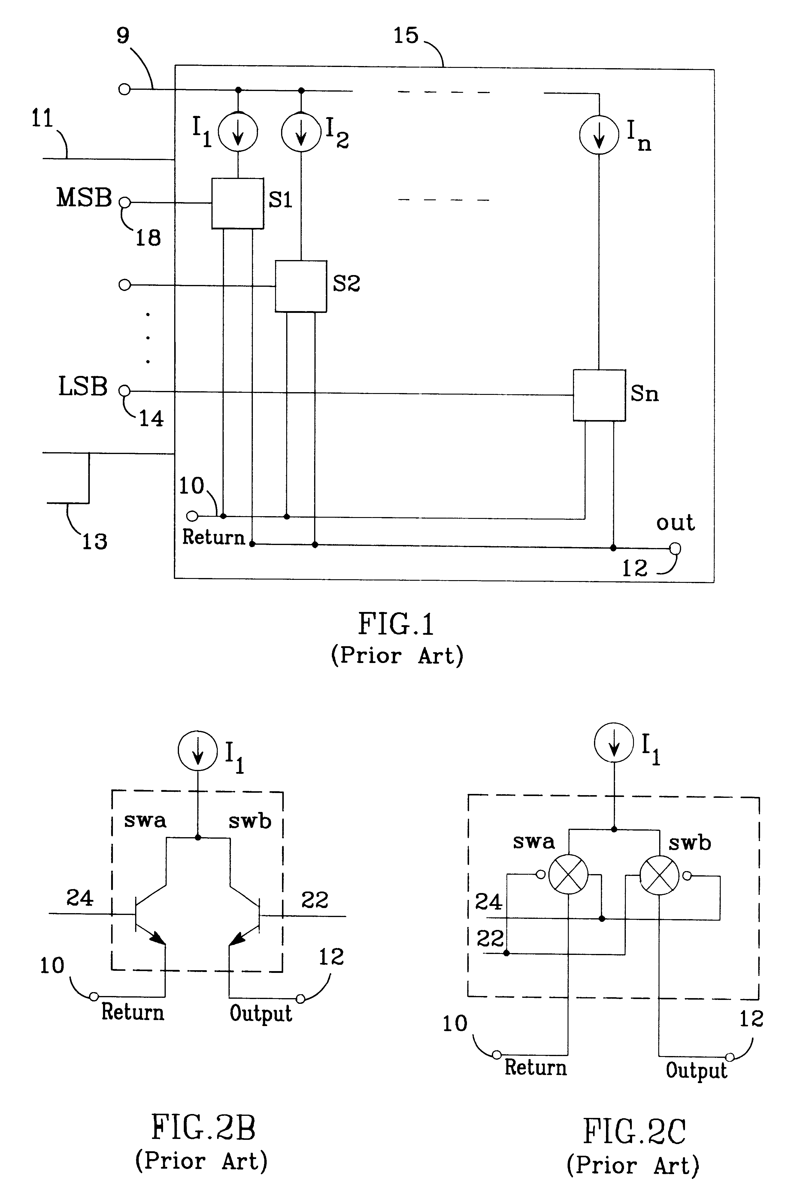
However, as will be explained in greater detail in relation to FIG. 2, there is often a delay introduced between the "make" and "break" actions of the switches S1-Sn, causing spurious signals, or "glitches", to appear at the output terminal 12.
Although filtering may eliminate or reduce to a tolerable level the contribution from some of the glitches, higher order harmonics, which alias back into the Nyquist bandwidth, cannot be filtered.
However, as described above, the delay between control signals TRUE and INVERTED sometimes place both switches swa and swb into conduction at the same time.
Not only is an elaborate enable signal required, glitches, which may create unfilterable spurious signals, are produced by the delay between the generation of TRUE and INVERTED control signals for the differential switch pair.

Method used


Image

  • Skewless differential switch and DAC employing the same
  • Skewless differential switch and DAC employing the same
  • Skewless differential switch and DAC employing the same

Examples


Embodiment Construction

The new switch 30 of FIG. 3 may be employed within a DAC, for example, as one of the differential switches S1-Sn illustrated in FIG. 1. The new switch 30 comprises a latch 32 with a binary input MSB and enable input ck. The latch 32 accepts a single binary signal at an MSB input, and produces de-skewed TRUE and INVERTED control signals at like-named outputs. These outputs are connected to the control terminals 34 and 36 of a conventional differential switch pair 38 which may be compose, for example, as described in the background section, of NPN or PNP bipolar transistors, N-channel of P-channel MOSFETs or CMOS analog switches.

The latch 32 accepts a binary signal at the input MSB, inverts the signal with an inverter INV3 and, under control of transfer switches TSW1 and TSW2, transfers the TRUE and INVERTED signals thus produced into storage elements 40 and 42. Outputs from the storage elements 40 and 42 are connected to the control inputs 34 and 36 of a differential switch pair comp...


PUM


Abstract

A differential switch accepts a binary control signal and its complement (which may be skewed with respect to the control signal) and latches both signals simultaneously. The latched output signals drive the control terminals of a differential switch pair which connects one of two terminals to a third terminal, depending upon the state of the control terminals. The differential switch may optionally include an inverter which complements the binary control signal, thus eliminating the need for external inversion of the control signal. The switch is particularly applicable for use in a digital to analog converter.

Description

BACKGROUND OF THE INVENTION1. Field of the InventionThe invention relates to the field of differential switches and, in particular, to differential switches operated under control of a single binary signal, as in the case of digital to analog converters (DACs).2. Description of the Related ArtBinary-control differential switches operate as single-pole double-throw switches and are employed in many applications such as DACs. Within such a switch, a single control terminal effects contact between a first conducting terminal and a second conducting terminal while breaking contact between the first conducting terminal and a third conducting terminal. Although the utility of such switches will be described in reference to their application within DACs, they may be used for many other applications.There are a number of conventional DAC architectures which employ differential switches. Some are current output, some are voltage output. For examples of both see, Analog-Digital Conversion Han...

Claims


Application Information

Patent Timeline
IPC IPC(8): H03K17/041H03K17/04
CPCH03K17/04106
Inventor MERCER, DOUGLAS A.ROBERTSON, DAVID H.STROUD, ERNEST T.REYNOLDS, DAVID
Owner ANALOG DEVICES INC
Learn More