Dental implant system

a technology of implant system and implant, which is applied in the field of dental implant system, can solve the problems of bone erosion and trauma, relative large trauma area, and risk of post-operative infection, and achieve the effect of reducing tissue trauma and minimal trauma

Inactive Publication Date: 2002-04-09
CENTPULSE DENTAL
View PDF42 Cites 21 Cited by
  • Summary
  • Abstract
  • Description
  • Claims
  • Application Information

AI Technical Summary

Benefits of technology

The implant system and method described above provides a rest surface for an overlying cantilevered bridge or denture which is anchored elsewhere in the jaw, on which the denture can rest and which accepts down pressure from the denture, reducing tissue trauma. Rest surfaces may be provided wherever needed, in conju

Problems solved by technology

This results in a relatively large area of trauma with a certain degree of pain to the patient and risk of post-operative infection.
Another problem with conventional implants is their length, which makes them difficult to implant in the distal jaw region, where there is insufficient depth to enable their insertion without interference with the mandibular nerve, without the assistance of a dental surgeon to locate the precise position of the nerve and ensure that the implant does not interfere with it.
A shorter cylindrical implant would not normally be suitable since it would

Method used


Image

  • Dental implant system
  • Dental implant system
  • Dental implant system

Examples


first embodiment

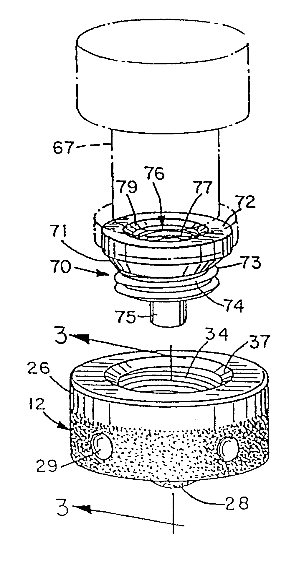
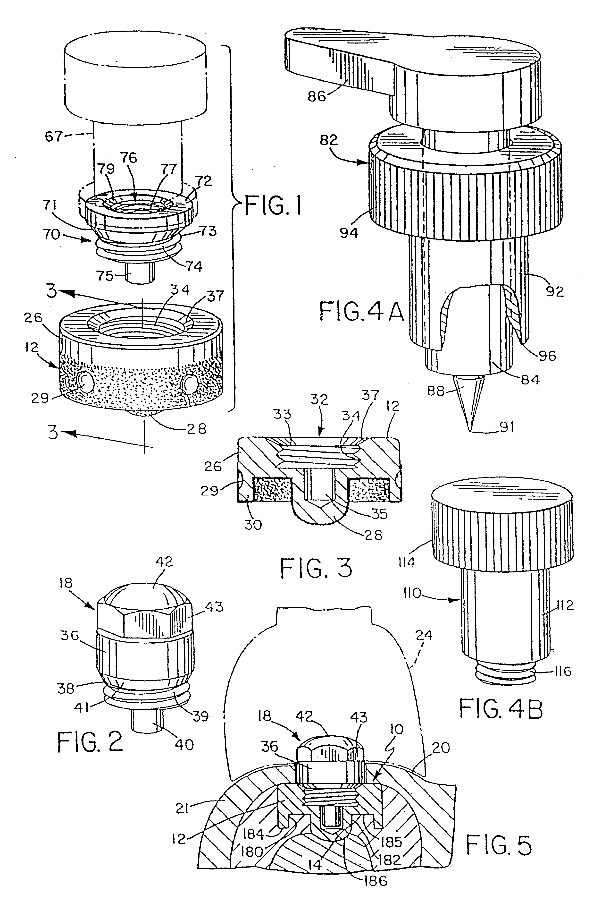
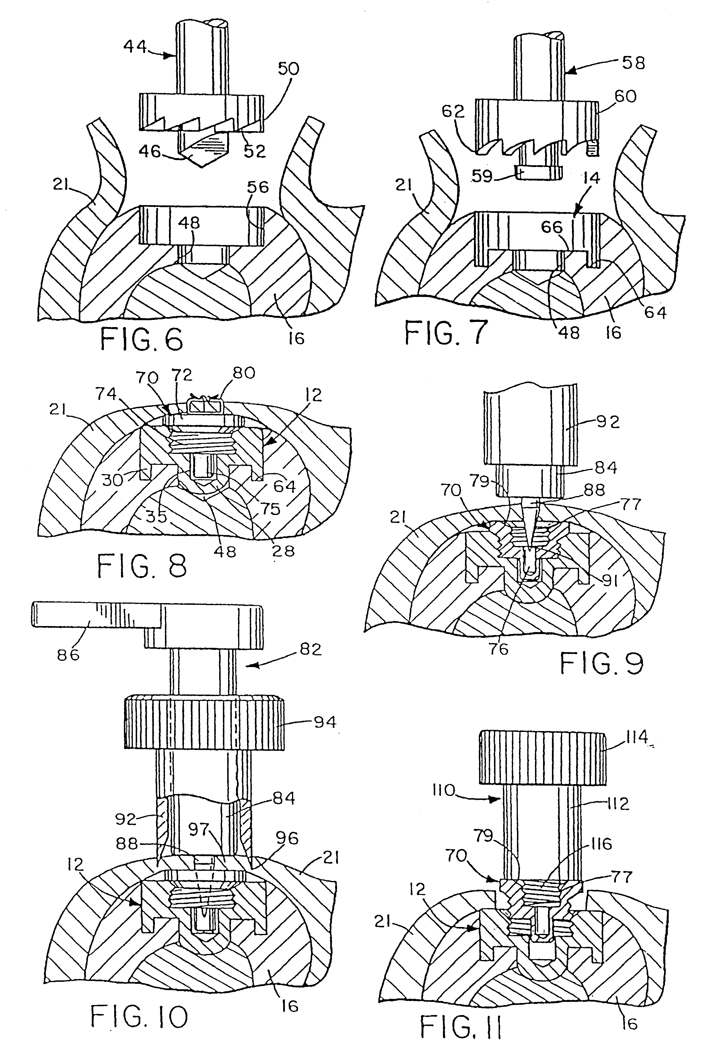
Healing screw 182 has a relatively short head portion 195 and a downwardly depending, screw threaded shaft portion 196 for mating engagement in the bore 192 of implant member 180, as illustrated in FIG. 18. The undersurface of head portion 195 seats in recessed area 190 and has a tapered annular surface portion 197 for seating on taper 191 around the recessed area 190, for accurate seating of the screw in bore 192. The upper surface of head 195 has a central, tool receiving bore 198 for receiving the end of a suitable tool for inserting the arrangement in a previously prepared bore in the jawbone, and also for receiving the end of locating tool 82 as described above in connection with the invention. Bore 198 is of hexagonal cross-section, and is designed to be removed by a suitable removal tool having a hexagonal end after location by tool 82.

second embodiment

The rest factor or member of the second embodiment is not illustrated in the drawings but will be similar or equivalent to rest factor 36 as illustrated in FIGS. 2 and 5 of the drawings apart from its lower surface and downwardly depending shaft portion, which will be identical to lower surface and shaft portion of the healing screw 182 for mating engagement in the bore 192 in implant member 180 after osseointegration is complete.

The modified method of inserting insert member 180 in the jaw will now be described with reference to FIGS. 15-17 of the drawings. This procedure can easily be carried out by a dentist, although a dental surgeon may also perform the procedure if desired. After the tissue overlying the implant site has been cut, a pilot dimple is formed at the center of the selected site. The width of the alveolar crest or ridge at the implant site is measured, and the largest possible diameter implant which will fit within the available width while leaving at least 1 / 2 mm o...


PUM


Abstract

A dental implant assembly is provided, as well as a system and method for exposing an embedded implant after osseointegration has taken place. The implant assembly comprises an implant member for embedding in the jaw and a rest factor member for securing to the implant member, the rest factor member having an upper rest surface just above the tissue level for opposing an overlying portion of a prosthesis anchored elsewhere in the jaw to form a non-retentive rest or support for accepting down pressure from the prosthesis. The implant member is relatively short and can be installed in distal jaw regions without interference with the mandibular nerve. A bore is cut out in the jaw for receiving the implant, inserting the implant and an attached healing screw in the implant. The implant site is closed and osseointegration takes place over an extended period. Subsequently, the implant site is uncovered, the healing screw is removed, and the rest factor member is secured in the implant.

Description

BACKGROUND OF THE INVENTIONThe present invention relates to a dental implant system.Dental implants are embedded in the jaw bone and serve to anchor one or more artificial teeth or dentures. Most implant systems involve a relatively long implant cylinder which is placed into a custom bored hole in the jawbone, then left for several months to allow healing and bone integration. Then the implant must be exposed for attachment of a dental prosthetic appliance such as a crown, denture, partial denture or bridge. This generally involves the dentist cutting out a flap of tissue which is peeled back to expose the implant, and secured by sutures after installing the prosthesis. This results in a relatively large area of trauma with a certain degree of pain to the patient and risk of post-operative infection.Another problem with conventional implants is their length, which makes them difficult to implant in the distal jaw region, where there is insufficient depth to enable their insertion wi...

Claims


Application Information

Patent Timeline
IPC IPC(8): A61C8/00
CPCA61C8/0018A61C8/0025A61C8/0089
Inventor ZUEST, MAX
Owner CENTPULSE DENTAL
Why Eureka
Try Eureka