
Apparatus for detecting leaks in a pressurized air conditioning or refrigeration system

a technology for applied in the field of apparatus for detecting leaks in pressurized air conditioning or refrigeration systems, can solve the problems of difficult to locate air conditioning or refrigeration system leaks, presently there is no cost effective way, etc., and achieves the effects of convenient transportation to a site, simple and easy operation, and convenient operation

Inactive Publication Date: 2003-12-09
CPS PROD CANADA
View PDF12 Cites 7 Cited by
  • Summary
  • Abstract
  • Description
  • Claims
  • Application Information

AI Technical Summary

Benefits of technology

In a more preferred embodiment, the tubular casing is fabricated out of transparent material and includes a plurality of gradient markings to aid in accurately dispensing a predetermined amount of the secondary fluid therefrom. In another embodiment, the canister further includes a threaded cap, to engage with the threaded nozzle when the canister is not in use, so as to prevent leakage of the secondary fluid through the threaded nozzle.
A still further object is to provide an apparatus for detecting leaks in a pressurized air conditioning or refrigeration system that is economical in cost to manufacture.

Problems solved by technology

There does not presently exist a cost effective way to accomplish the task of inserting a predetermined amount of lubricant into a pressurized system.
Added to this, is the fact that when a technician arrives on site they are faced with a myriad number of systems with service connection access ranging from the accessible to the acrobatic and often cramped working conditions.
Furthermore, air conditioning or refrigeration system leaks are difficult to locate because refrigerants are generally odorless and colorless gases.

Method used


Image

  • Apparatus for detecting leaks in a pressurized air conditioning or refrigeration system
  • Apparatus for detecting leaks in a pressurized air conditioning or refrigeration system
  • Apparatus for detecting leaks in a pressurized air conditioning or refrigeration system

Examples


Embodiment Construction

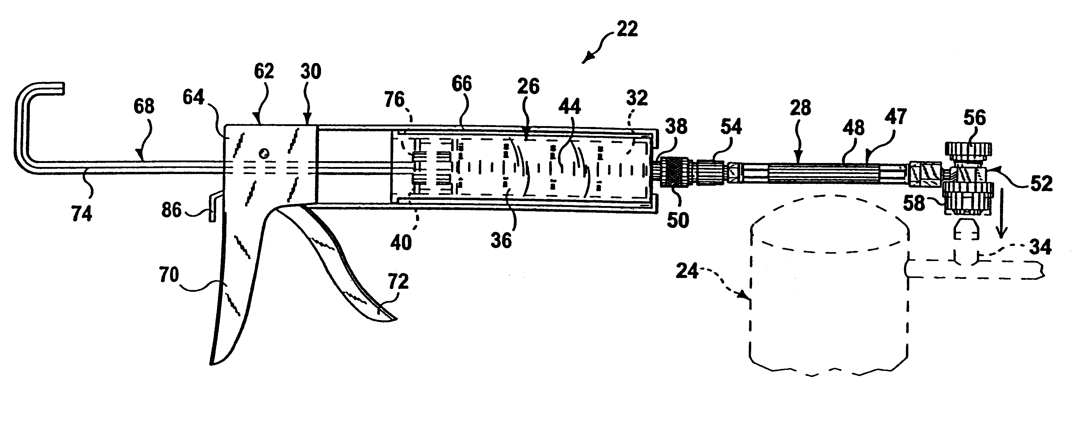
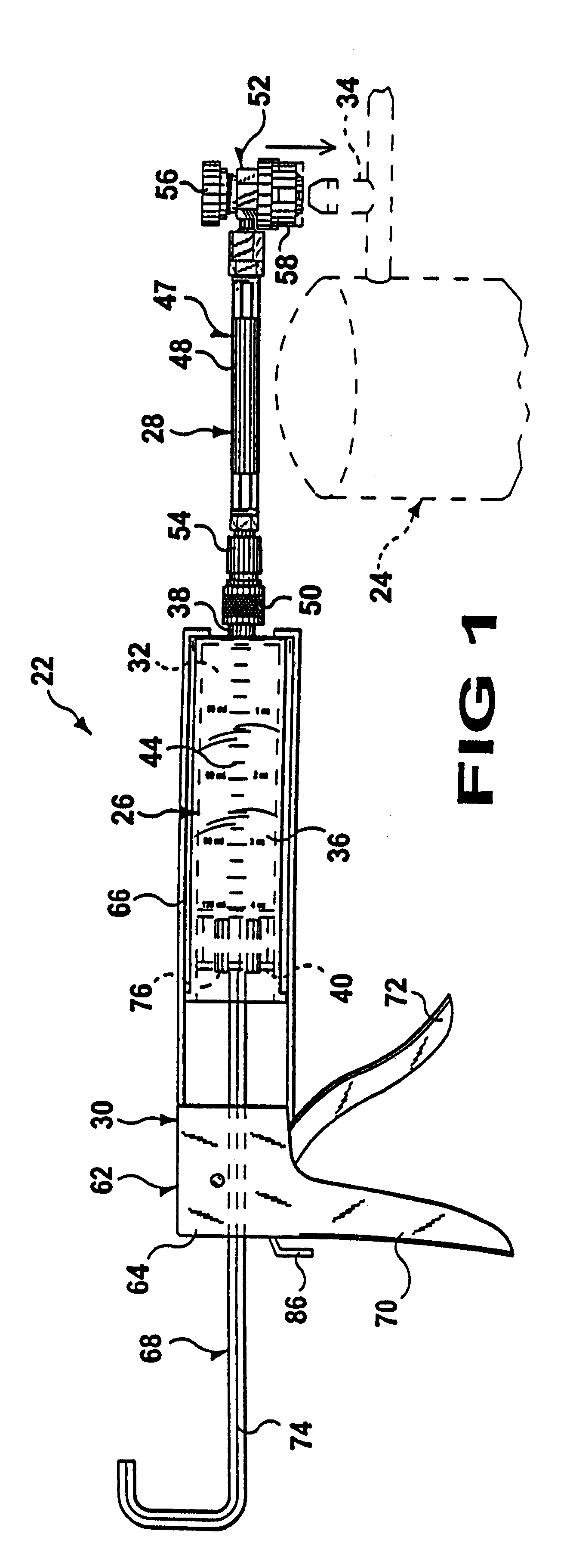
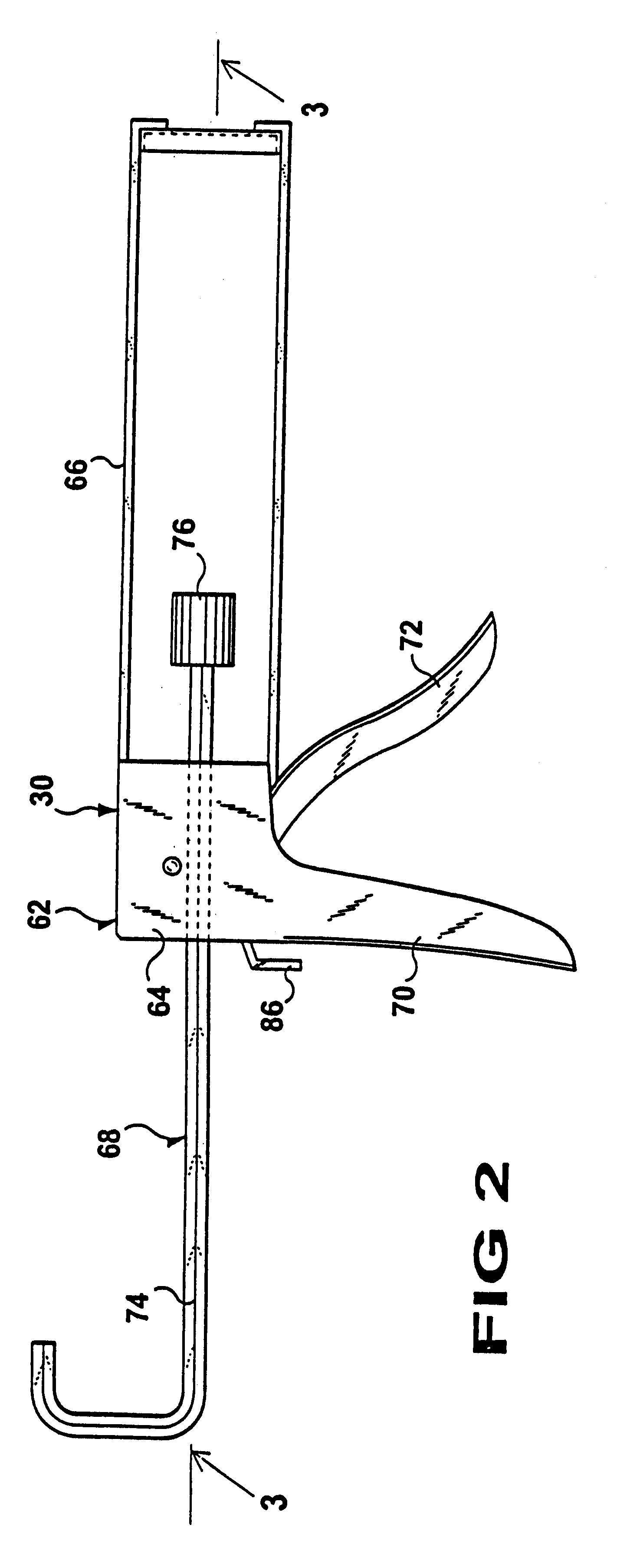
Turning now descriptively to the drawings, in which similar reference characters denote similar elements throughout the several views, FIG. 1 illustrates the present invention being an apparatus 22 for detecting leaks in a pressurized air conditioning or refrigeration system 24. With regard to the reference numerals used, the following numbering is used throughout the various drawings figures. 22 charging apparatus 24 pressurized system 26 canister of 22 28 fluidly coupling facility of 22 30 lubricant or secondary fluid forcing assemblage of 22 32 lubricant and / or fluorescent dye of 26 33 central nipple or inner nozzle 34 service valve of 24 35 internal thread 36 tubular casing of 26 37 outer nozzle 38 threaded nozzle of 26 on 36 39 external thread 40 piston of 26 in 36 42 transparent material for 36 44 gradient marking on 36 46 threaded cap of 26 on 38 47 connector assembly for 28 48 flexible conduit of 47 50 threaded fitting of 47 on 48 52 release valve of 47 on 48 54 one-way chec...


PUM

PropertyMeasurementUnit
pressureaaaaaaaaaa
flexibleaaaaaaaaaa
transparentaaaaaaaaaa

Abstract

An apparatus (22) and method for detecting leaks in a pressurized air conditioning or refrigeration system (24) comprising a cartridge (26) is described. A facility (28) is for fluidly coupling the cartridge (26) to the pressurized system (24). An assemblage (30) is for forcing a secondary fluid (32) out of the cartridge (26), through the fluidly coupling facility (28) and into a service valve (34) of the pressurized system (24). The cartridge (26) has a first open end with an inner nozzle (33) which connects to the system being charged and an outer nozzle (37).

Description

BACKGROUND OF THE INVENTION1. Field of the InventionThe instant invention relates generally to the field of pressurized fluid systems and more specifically it relates to an apparatus for detecting leaks in a pressurized air conditioning or refrigeration system. The purpose of the apparatus is to provide the technician with a simple method of injecting a predetermined amount of a secondary fluid, e.g., a fluorescent dye, and / or lubricant into a pressurized system.2. Description of the Prior ArtNumerous pressurized fluid systems have been provided in the prior art that are adapted to operate optimally within a certain pressure range. If the internal pressure falls below this range, the system needs to be recharged with an appropriate lubricant. While these units may be suitable for the particular purpose to which they address, they would not be as suitable for the purposes of the present invention as heretofore described.There does not presently exist a cost effective way to accomplis...

Claims


Application Information

Patent Timeline
Patent Type & Authority Patents(United States)
IPC IPC(8): F17C13/00F17C5/00F16N37/00F16N37/02F25B45/00F25B31/00
CPCF16N37/02F17C5/00F17C13/00F25B31/002F25B45/00F25B2345/006
Inventor TRIGIANI, PHIL
Owner CPS PROD CANADA
Learn More