Injection molding machine having a platen for uniform distribution of clamping forces

a technology of injection molding machine and clamping force, which is applied in the direction of presses, manufacturing tools, food shaping, etc., can solve the problems of uncompensated mold face bending, possibility of flashing still exists, and the method and apparatus by which this is achieved are quite complex, and achieve the effect of reducing clamping pressure, light weight and quick mold cycle operation

Inactive Publication Date: 2006-07-18
HUSKY INJECTION MOLDING SYST LTD
View PDF9 Cites 6 Cited by
  • Summary
  • Abstract
  • Description
  • Claims
  • Application Information

AI Technical Summary

Benefits of technology

[0013]A further object of the invention is to provide a light weight mold carrying platen that provides substantially flat and parallel mold mounting faces during clamp-up and thus requires lower clamping pressure for a giving injection molding process.
[0014]Still yet another object of the present invention is to provide an injection molding machine having a structurally optimized and light weight platen that allows for quicker mold cycle operations, thereby increasing the throughput of a given injection molding machine.
[0015]Yet another object of the present invention is to provide an injection molding machine having a platen which uses less energy per operation cycle of the injection molding machine due to the reduced weight of the movable platen.
[0016]The foregoing objects are achieved by the injection molding machine of the present invention. The machine includes a stationary platen having a first mold half, at least one movable platen having a second mold half for forming a mold with said first mold half, means for guiding said movable platen relative said stationary platen, and means for injecting molten resin into said mold. For one of the platens a back face is positioned central to the platen for the connection to a pressure source such as a hydraulic cylinder. Parallel to and spaced from the back face is a front face for carrying a mold half, and protruding rearward from the periphery of the front face is a structural wall. Extending from the back face to the front face is a plurality of spaced ribs which are rigidly affixed to the structural wall in a structurally optimized pattern. Means for uniformly directing the clamping force from the center of the back face to the front face to reduce localized bending of the mold face is provided.

Problems solved by technology

As a result, under the clamp-up force the center of the platens separate causing a gap between the mold halves, and in some cases, the formation of flash is a by-product.
While Baird compensates for deflection, the method and apparatus by which this is achieved is quite complex requiring individual designs for particular forces to be generated with particular molds.
Accordingly, despite the design of the mold platen of FIGS. 5a and 5b, mold face bending is not compensated for and the possibility of the creation of flash still exists.
Since both sides of the platen bend, the supports at the corners of the tie bars also bend resulting in uneven loading of the tie bar supports.
This causes bending of the tie bars and high stress concentrations leading to premature fatigue failure.

Method used


Image

  • Injection molding machine having a platen for uniform distribution of clamping forces
  • Injection molding machine having a platen for uniform distribution of clamping forces
  • Injection molding machine having a platen for uniform distribution of clamping forces

Examples


Embodiment Construction

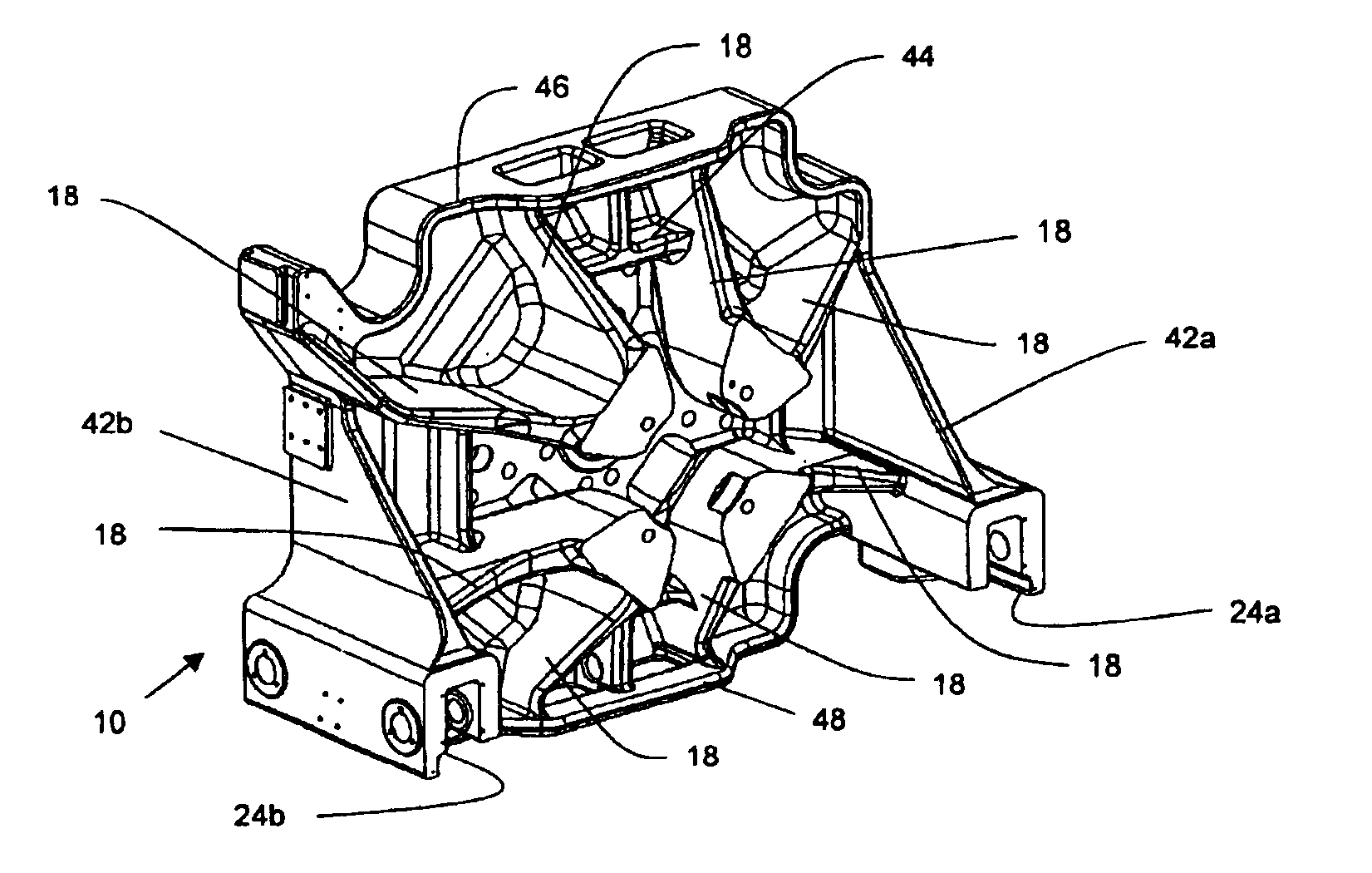
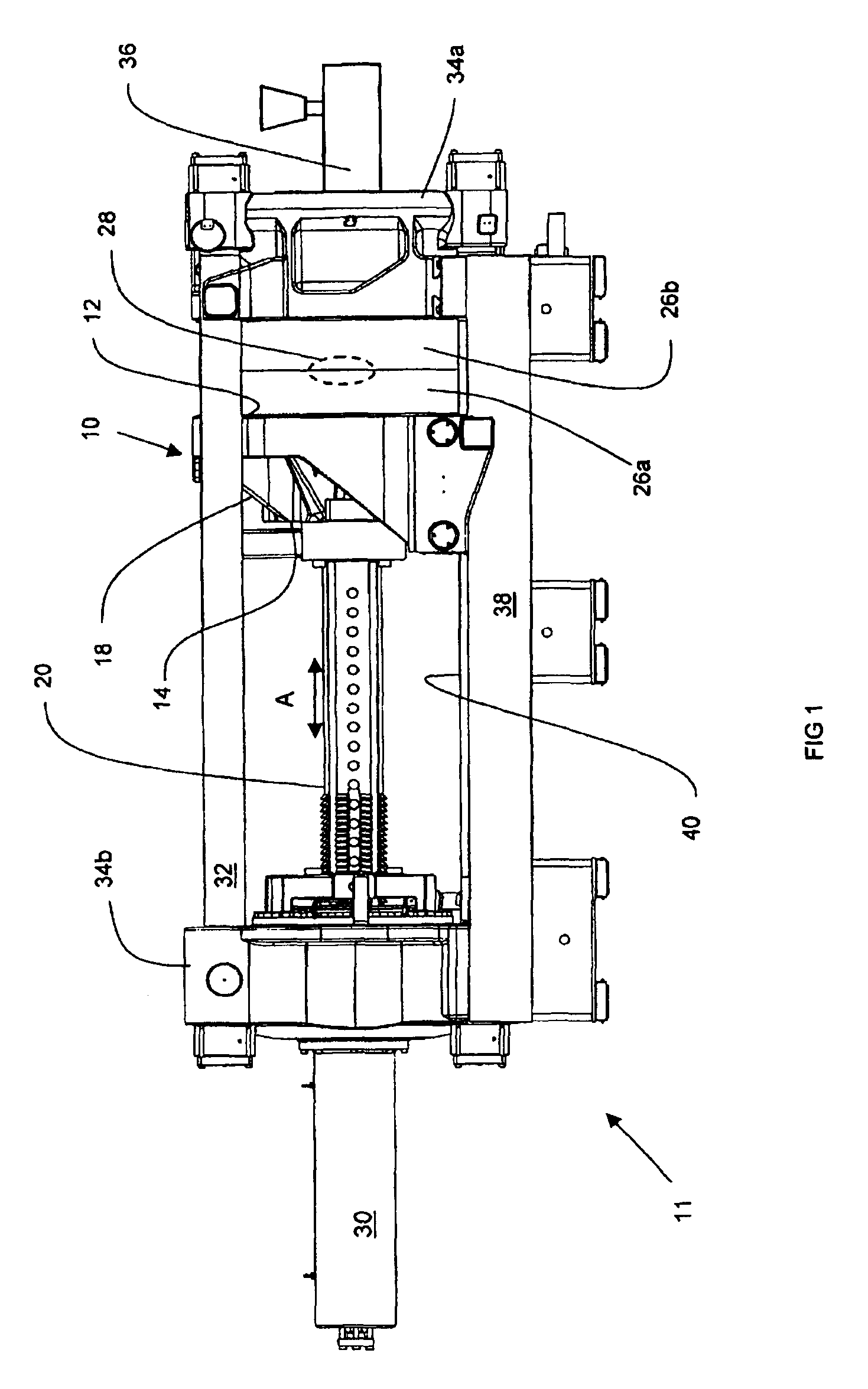
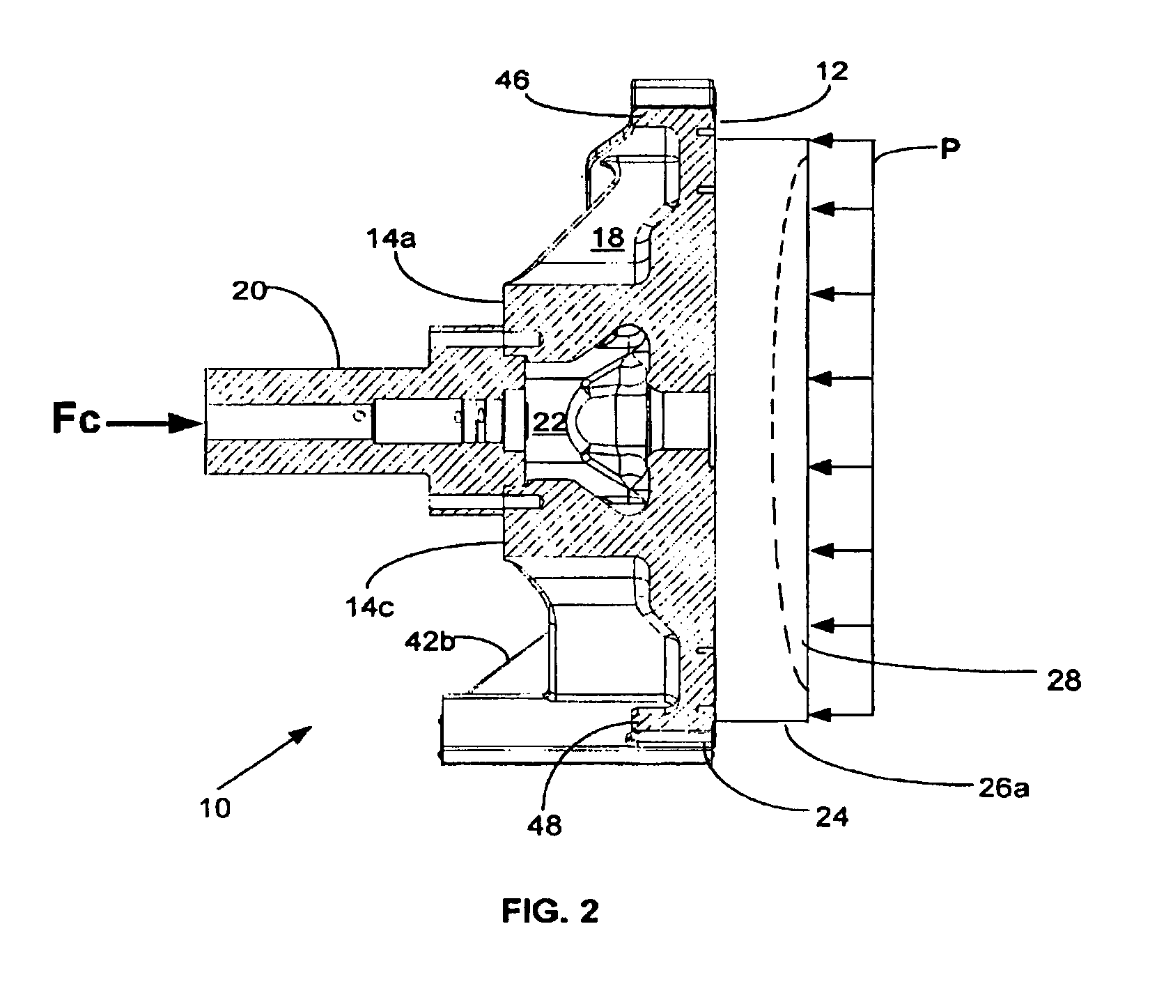
[0024]Referring to FIG. 1, an injection molding machine 11 is generally shown which uses at least one movable platen 10 in accordance with the present invention. Rigidly affixed to a central location of a back face 14 of the movable platen 10 is at least one clamp column 20 which allows the platen to be opened and closed (arrow A) by a hydraulic cylinder 30. The movable platen 10 rides along a rail 40 affixed to a machine base 38. A plurality of tie bars 32 run the length of the machine 11 and connect to spaced apart first and second stationary platensplaten 34a and clamp block 34b respectively.

[0025]A first mold half 26a is removably attached to a front face 12 of the movable platen 10. A second mold half 26b is removably mounted to second stationary platenclamp block 34b such that mold halves 26a and 26b form a mold cavity 28 therein when brought into contact during clamp-up by clamp column 20. Attached to the first stationary platen 34a and in communication with mold cavity 28 ...


PUM

PropertyMeasurementUnit
forceaaaaaaaaaa
thicknessaaaaaaaaaa
heightaaaaaaaaaa

Abstract

An injection molding machine includes a movable platen specifically adapted to uniformly distribute a clamp force to the mold half surfaces thereby reducing localized deflections and unwanted flash on the molded article.

Description

[0001]This application is a reissue of application Ser. No. 09 / 699,927 filed Oct. 30, 2000, now U.S. Pat. No. 6,439,876.BACKGROUND OF THE INVENTION[0002]1. Field of the Invention[0003]This invention relates to a structure for a movable platen for supporting a portion of an injection mold in an injection molding machine. More particularly, the present invention relates to a movable mold supporting platen that has improved rigidity that is slidably carried on an injection molding machine base.[0004]2. Summary of the Prior Art[0005]In general, machines for injection molding of plastics articles include a pair of fixed platens that are spaced from each other and that are interconnected by generally four parallel tie bars that have their axes positioned to define a rectangular array. One of the fixed platens remains stationary and is adapted to support one portion of a two or multiple piece injection mold that when assembled or engaged defines a mold cavity to correspond with the outline...

Claims


Application Information

Patent Timeline
Patent Type & Authority Patents(United States)
IPC IPC(8): B29C45/64B29C45/26B29C45/17B29C45/70
CPCB29C45/1744
Inventor GLAESENER, PIERRE
Owner HUSKY INJECTION MOLDING SYST LTD
Why Eureka
Try Eureka