
Optically driven therapeutic radiation source having a spiral-shaped thermionic cathode

a radiation source and spiral-shaped technology, applied in radiation therapy, electric discharge tubes, therapy, etc., can solve the problems of increasing the risk of radiation exposure to non-cancer tissues and organs, affecting the safety of handling personnel and the environment, and affecting the efficiency of the miniaturized thermionic cathod

Inactive Publication Date: 2010-09-21
CARL ZEISS SMT GMBH
View PDF18 Cites 0 Cited by
  • Summary
  • Abstract
  • Description
  • Claims
  • Application Information

AI Technical Summary

Benefits of technology

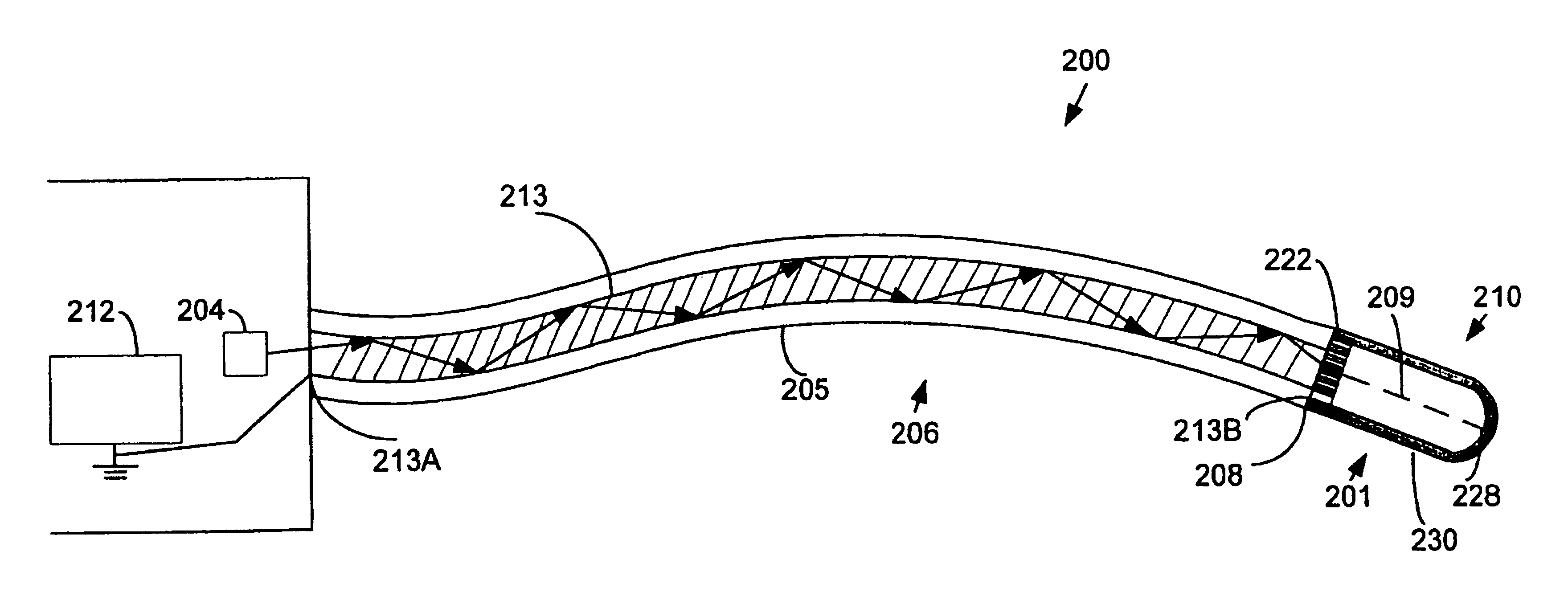
[0015]The invention relates to a highly efficient, miniaturized source of therapeutic radiation, such as x-rays. The therapeutic radiation source has an optically-driven thermionic cathode that is spiral-shaped. In this way, heat loss due to thermal conduction within the thermionic cathode is minimized.
[0018]In one embodiment, the spiral-shaped thermionic cathode is made of a spiral-shaped conductive element. The spiral-shaped conductive element has a plurality of spaced apart turns, and defines an interstitial spacing between each successive turn of said conductive element. Because the spiral-shaped conductive element is enclosed within the substantially evacuated interior region, heat transfer across the interstitial spacing between each adjacent turn of the conductive element is essentially eliminated. By minimizing heat lost by thermal conduction, the efficiency of the miniaturized thermionic cathode is increased.

Problems solved by technology

This treatment suffers from the disadvantage that tissue disposed between the radiation source and the target is exposed to radiation.
Non-cancerous tissues and organs are therefore also damaged by the penetrating x-ray radiation.
Handling and disposing of such radioisotopes, however, may impose considerable hazards to both the handling personnel and the environment.
In conventional x-ray tubes, for example, thermal vaporization of the cathode filament is frequently responsible for tube failure.
Also, the anode heated to a high temperature can cause degradation of the radiation output.
While a photocathode avoids such problems, there are difficulties inherent in fabricating the photocathode, because photocathode fabrication should preferably be done in a vacuum.
These reflector elements cannot reduce, however, heat loss that is caused by thermal conduction in the thermionic cathode.

Method used


Image

  • Optically driven therapeutic radiation source having a spiral-shaped thermionic cathode
  • Optically driven therapeutic radiation source having a spiral-shaped thermionic cathode
  • Optically driven therapeutic radiation source having a spiral-shaped thermionic cathode

Examples


Embodiment Construction

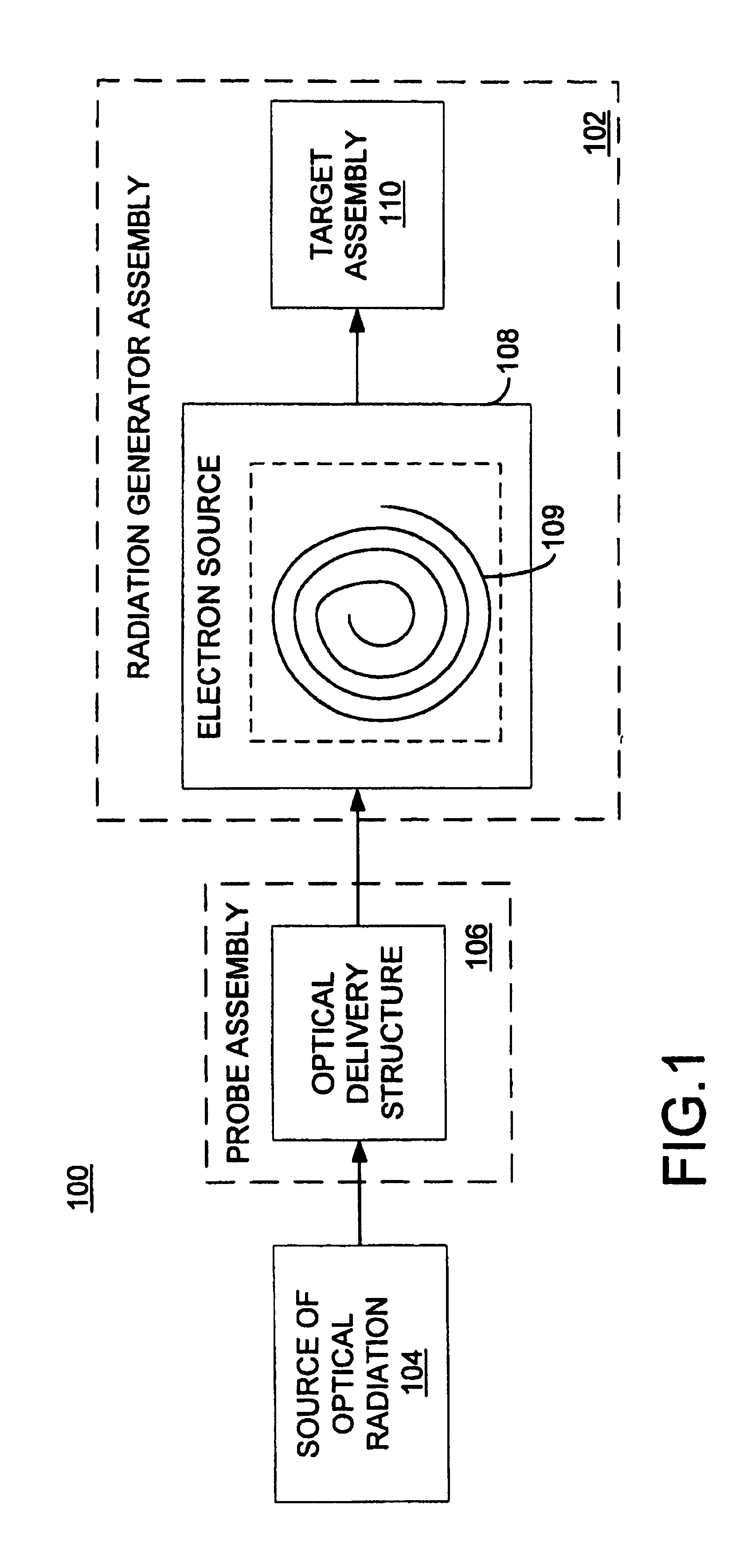
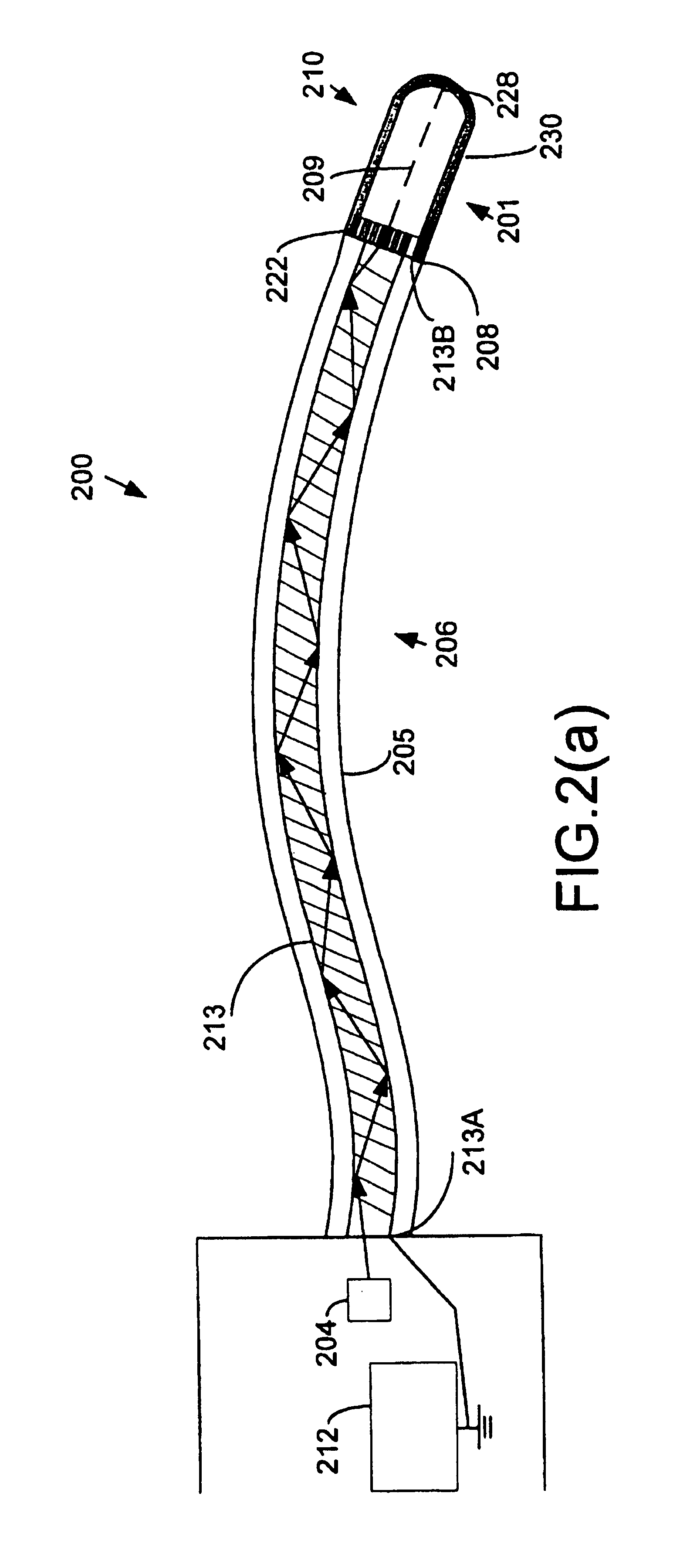
[0024]The present invention is directed to a miniaturized, low power therapeutic radiation source which includes an electron-beam activated therapeutic radiation source, and which uses a laser-heated thermionic cathode. As described in the PHLL-155 application, use of a thermionic cathode that is laser-heated significantly reduces the power requirements for such therapeutic radiation sources. The present invention features the use of a spiral-shaped thermionic cathode, which is configured so as to minimize energy lost from the incident laser radiation due to thermal conduction within the thermionic cathode. In this way, the power requirements for generating therapeutic radiation in such miniaturized radiation sources are further reduced.

[0025]FIG. 1 is a schematic block diagram of an overview of one embodiment of a therapeutic radiation source 100, constructed according to the present invention, and including a spiral-shaped, laser-heated thermionic cathode. In overview, the system ...


PUM


Abstract

A therapeutic radiation source includes a spiral-shaped, laser-heated thermionic cathode. A fiber optic cable directs a beam of radiation, having a power level sufficient to heat at least a portion of the electron-emissive surface to an electron emitting temperature, from a laser source onto the cathode. The cathode generates an electron beam along a beam path by thermionic emission, and strikes a target positioned in its beam path. The target includes radiation emissive material that emits therapeutic radiation in response to incident accelerated electrons from the electron beam. The spiral-shaped conductive element has a plurality of spaced apart turns, and is disposed in a vacuum. An interstitial spacing is defined between adjacent turns, so that heat transfer across the spacing between each adjacent turn is essentially eliminated, thereby substantially reducing heat loss in the cathode caused by thermal conduction.

Description

CROSS-REFERENCE TO RELATED APPLICATIONS[0001]Not ApplicableSTATEMENT REGARDING FEDERALLY SPONSORED RESEARCH[0002]Not ApplicableREFERENCE TO MICROFICHE APPENDIX[0003]Not ApplicableFIELD OF THE INVENTION[0004]The present invention relates to therapeutic radiation sources, and in particular to miniaturized, highly efficient, optically-driven therapeutic radiation sources.BACKGROUND OF THE INVENTION[0005]In the field of medicine, radiation may be used for diagnostic, therapeutic and palliative purposes. For example, the therapeutic use of radiation such as x-rays and y-rays may involve eradicating malignant cells. Conventional radiation treatment systems used for medical treatment, such as linear accelerators that produce high-energy x-rays, utilize a remote radiation source external to the targeted tissue. A beam of radiation is directed at the target area, for example a tumor inside the body of a patient. The x-rays penetrate the patient's body tissue and deliver radiation to the canc...

Claims


Application Information

Patent Timeline
Patent Type & Authority Patents(United States)
IPC IPC(8): A61N5/10H01J35/32
CPCA61N5/1001H01J35/32H01J2235/164H01J35/064
Inventor DINSMORE, MARK
Owner CARL ZEISS SMT GMBH
Learn More