Throttle valve control device for an internal combustion engine

a control device and internal combustion engine technology, applied in the direction of electric control, ignition automatic control, speed sensing governors, etc., can solve the problems of automobiles not being able to travel at automobiles cannot be able to continue to travel at a desirable speed, and automobiles cannot be able to achieve the speed of 30 km/h, reducing torque, and reducing electrical load on the engine

Inactive Publication Date: 2011-11-22
HITACHI AUTOMOTIVE SYST LTD
View PDF10 Cites 4 Cited by
  • Summary
  • Abstract
  • Description
  • Claims
  • Application Information

AI Technical Summary

Benefits of technology

[0022]An object of the present invention is to provide a motor-driven throttle valve control device for an internal combustion engine, in which torque required to be produced by a throttle valve motor can be reduced by reducing torque for making the closing operation of a throttle valve starting from the position defined by a default stopper, whereby the throttle valve motor can be miniaturized and hence the electrical load against the engine is reduced.

Problems solved by technology

In such a case, a throttle valve is rapidly returned by a return spring to a full close position or an idle position, with the result that a traveling automobile is decelerated drastically.
Then, after the throttle valve is returned to the full close position, the automobile can no longer continue to travel at a desirable speed, because the engine can not produce sufficient torque with such opening of the throttle valve.
If the throttle valve is allowed to stand at the full close position for a long period of time after the engine stops, combustion products, such as tar and carbon, accumulate and adhere between the throttle valve and an inner wall of an intake pipe so that the throttle valve is fixed to the inner wall and experiences difficulty in being opened again by the torque of the driving motor.
With such a rotational speed of the engine, however, an automobile can never travel at the speed of 30 km / h, for example.
Under the condition of the limp-home travel, the opening of the throttle valve is maintained at a value to attain the aforesaid minimum safety, but the opening can be no longer adjusted, even if an acceleration pedal is operated.
Namely, the engine gets into a runaway condition.
Of course, if a throttle valve motor operates normally, the default stopper is unnecessary and awkward, because desirably the motor can control the opening of a throttle valve without any limitation between the position defined by the full close stopper and the full open position, in proportion to the depression amount of an acceleration pedal.

Method used


Image

  • Throttle valve control device for an internal combustion engine
  • Throttle valve control device for an internal combustion engine
  • Throttle valve control device for an internal combustion engine

Examples


first embodiment

[0052]Referring first to FIGS. 7 and 8, a basic construction and its operational principle of the present invention will be explained.

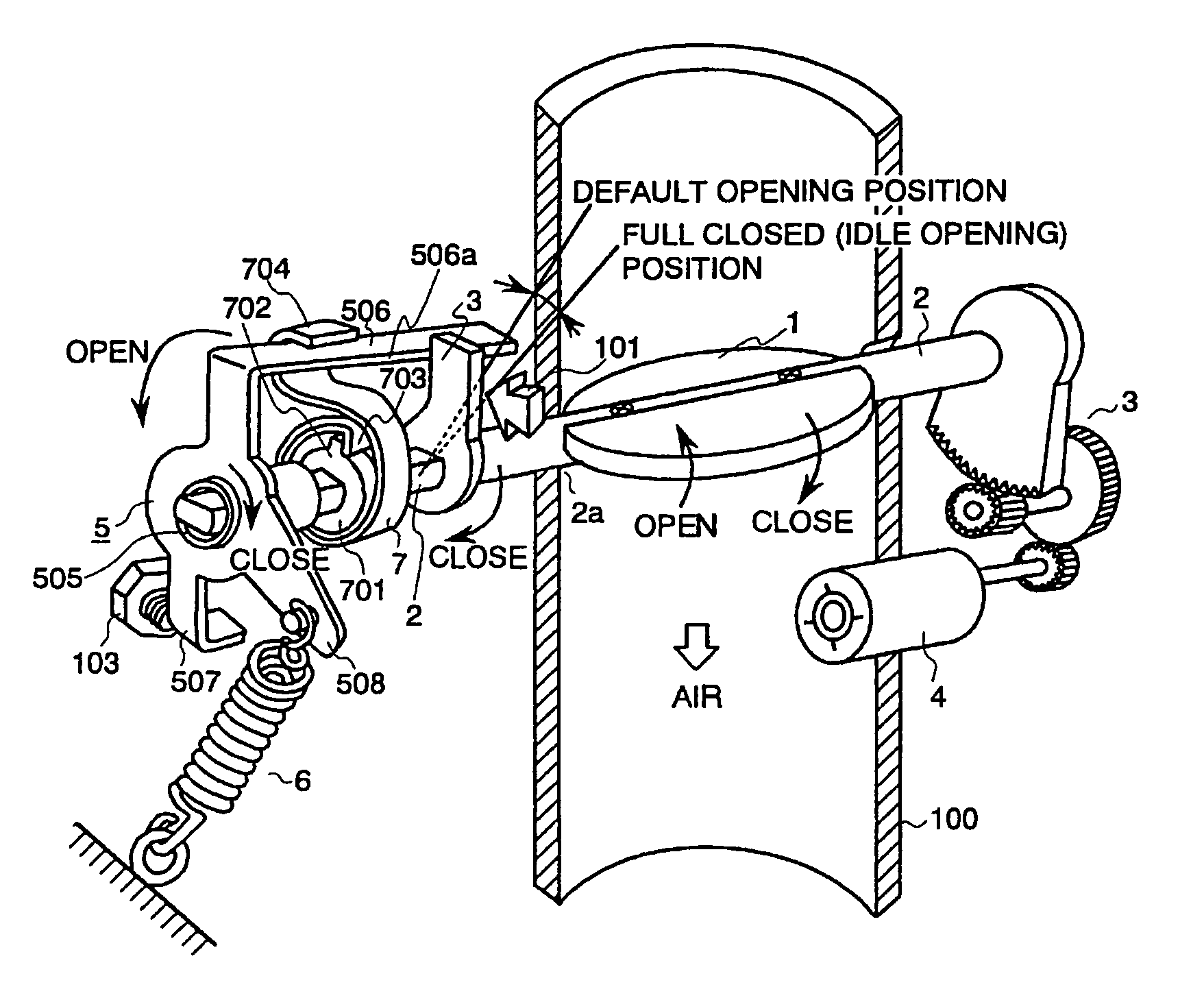
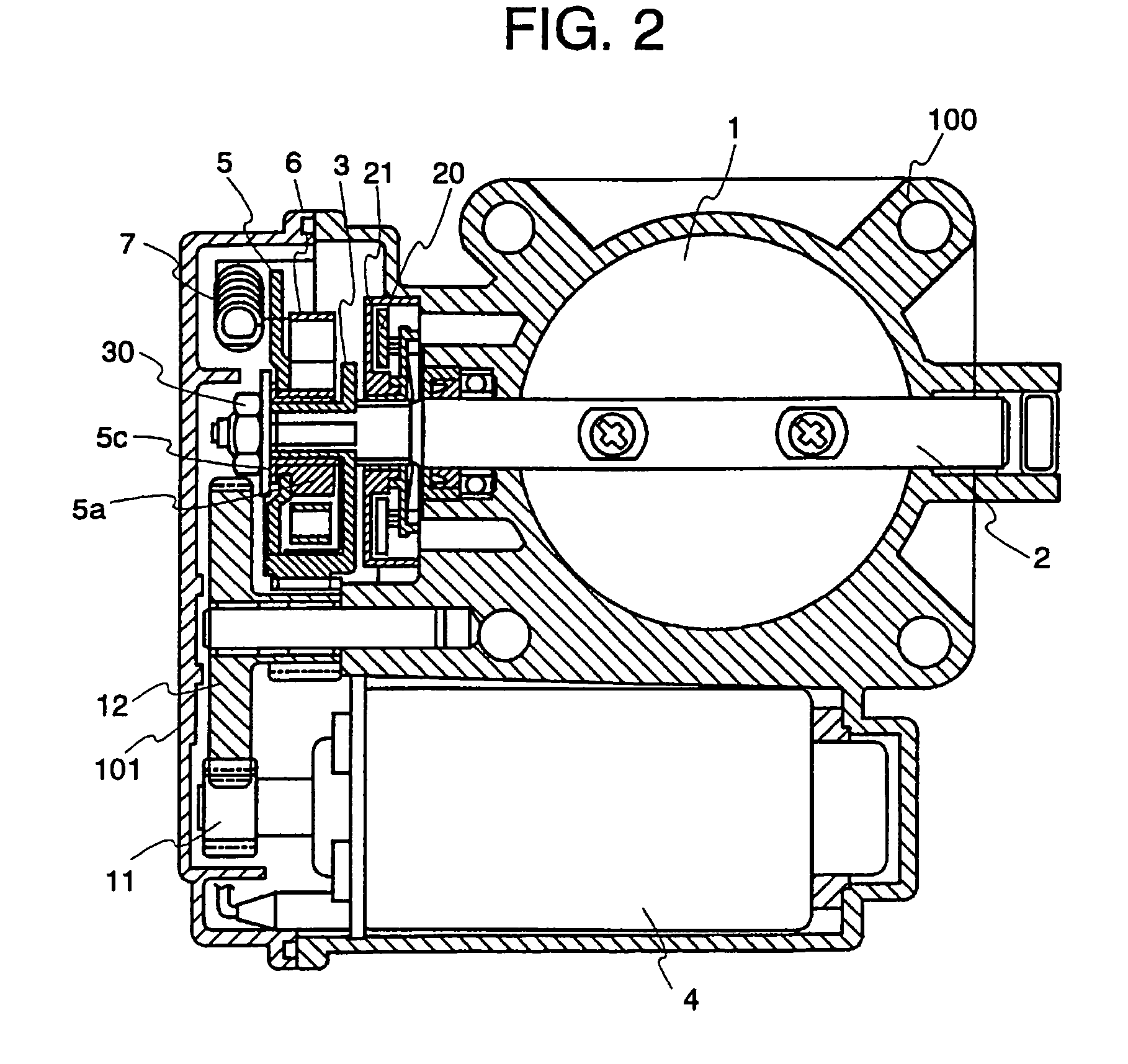
[0053]In FIG. 7, air flowing through intake pipe 100 is adjusted by the throttle valve 1 which is fixed to the throttle valve shaft 2. Reduction gears 3 are attached at the end of the throttle shaft 2. Rotating torque of the throttle valve motor 4 is transmitted to the throttle valve 1 through the gears 3, whereby the opening of the throttle valve 1 can be adjusted.

[0054]The rotation of the motor 4 is controlled in proportion to the depression amount of the acceleration pedal and therefore the opening of the throttle valve 1 is adjusted by the acceleration pedal.

[0055]Coupling lever 5 is supported by the throttle shaft 2, but can rotate independently therefrom. The lever 5 is energized toward the default stopper 103 by the default spring 7. The default spring 7 may be of an extension type or a compression type. If the throttle valve motor 4 is not fed...

second embodiment

[0089]Referring first to FIG. 9, however, description will be made of the principle of the

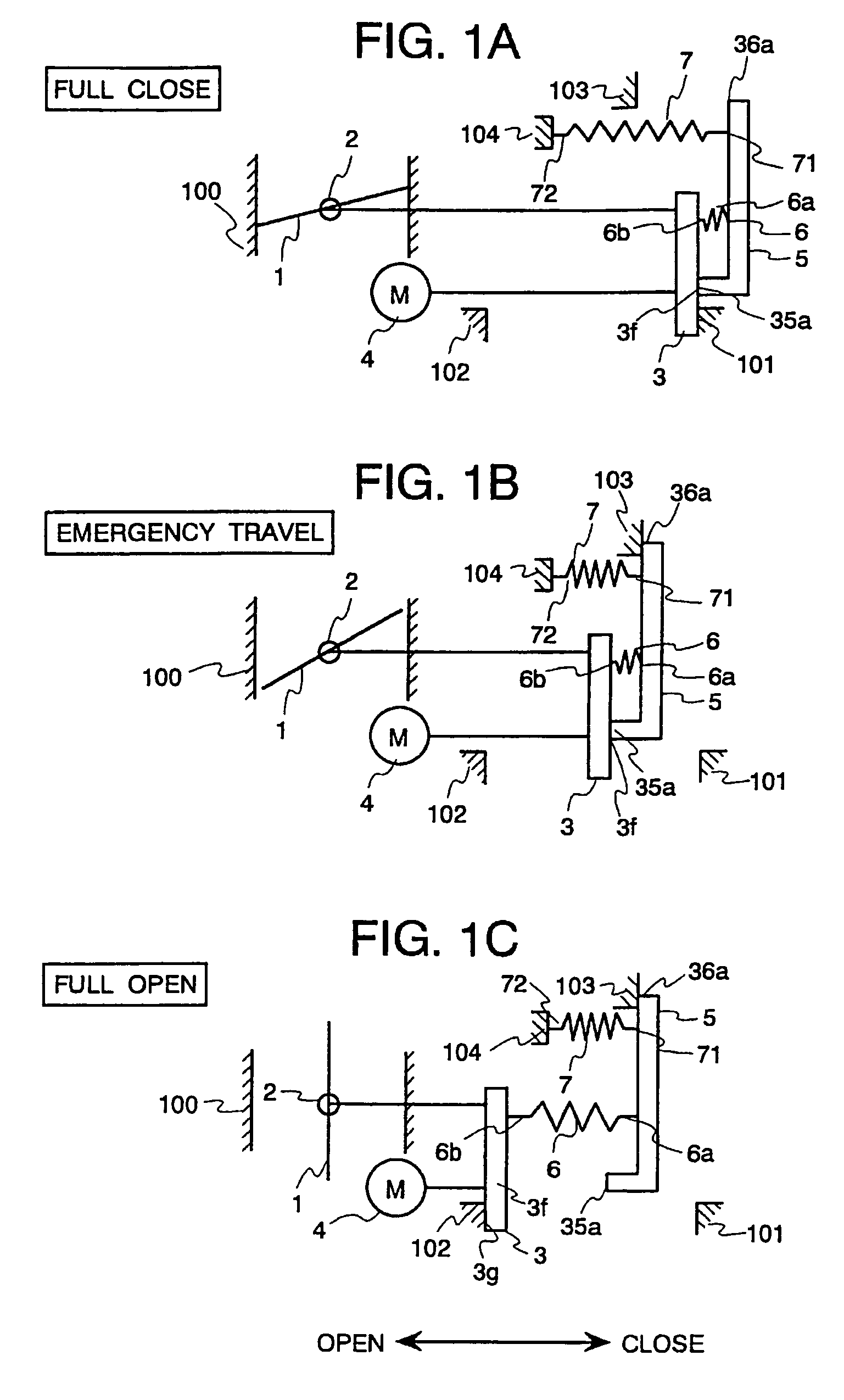
[0090]In FIG. 9, the throttle valve 1 is attached to the throttle valve shaft 2 which is rotated by the throttle valve motor 4 clockwise or counterclockwise through the reduction gear 3 in the same manner as in FIG. 7. The coupling lever 5 is arranged rotatably in relation to the throttle shaft 2 which is also the same as in FIG. 7. The following are the differences from FIG. 7:[0091](1) the throttle valve 1 is closed at the default position by the return spring 6 through the coupling lever 5; and[0092](2) the default spring 7 is provided between the throttle valve 1 and the coupling lever 5.[0093]The above structural differences cause the following operational differences:[0094](a) from the default position to the full close stopper, the throttle shaft 2 rotates independently, separated from the coupling lever 5. At this time, force of the default spring 7 acts directly on the throttle shaft 2...


PUM


Abstract

A motor-driven throttle valve control device has a throttle shaft and a coupling lever rotatably provided on the shaft, both being coupled by a spring. A default spring energizes the coupling lever toward a position of the default opening of the throttle valve. The throttle shaft rotates separately from the coupling lever in the direction of the full open throttle valve from a point at which the coupling lever comes into contact with a stopper defining the default position and, together with the coupling lever, in the full close direction of the throttle valve from the point. Thereby, the throttle valve can be kept at the default position by the default spring through the coupling lever when a motor driving the throttle valve is not powered.

Description

BACKGROUND OF THE INVENTION[0001]The present invention relates to a throttle valve control device for an internal combustion engine, and more particularly to a throttle valve control device with a motor-driven throttle valve.[0002]A conventional throttle valve control device is disclosed in JP-A-63-150449 (1988), and U.S. Pat. Nos. 4,947,815 and 4,735,179 (the last one being owned by the same assignee as this application).[0003]As discussed in the above documents, one of the most important things in a throttle valve device driven by an actuator, such as a DC motor or a step motor, is that the minimum safety can be secured even against a fault in the actuator.[0004]With the aforesaid “minimum safety”, the following is meant; i.e., even in the event of occurrence of a fault in a throttle valve actuator, an engine can produce torque of a certain magnitude, whereby an automobile can travel at a predetermined speed, e.g. 30 km / h or so, to reach a nearby repair shop. According to circumst...

Claims


Application Information

Patent Timeline
Patent Type & Authority Patents(United States)
IPC IPC(8): F02D11/10F02D9/02F02B75/12F02D9/00F02D9/10F02D35/00F02D37/02F02D41/22F02D43/00F02P5/15
CPCF02D9/02F02D9/1065F02D11/10F02D11/107F02D37/02F02B2075/125F02D31/008F02D2009/0262F02D2009/0269F02D2009/0277F02D2011/102F02D2041/227Y02T10/123Y02T10/12
Inventor YAMADA, HIROYUKIKAMIMURA, YASUHIROONO, KENJIISOZAKI, NORIHIRO
Owner HITACHI AUTOMOTIVE SYST LTD
Why Eureka
Try Eureka