Water labricating metal plastic bush and producing method
A metal plastic and production method technology, applied in the directions of hydropower, bearing components, shafts and bearings, etc., can solve the problems of short service life, difficult installation and debugging, large running swing of the unit, etc., to improve the running accuracy and wear resistance. Strong and anti-friction effect
- Summary
- Abstract
- Description
- Claims
- Application Information
AI Technical Summary
Problems solved by technology
Method used
Image

Examples
Embodiment 1
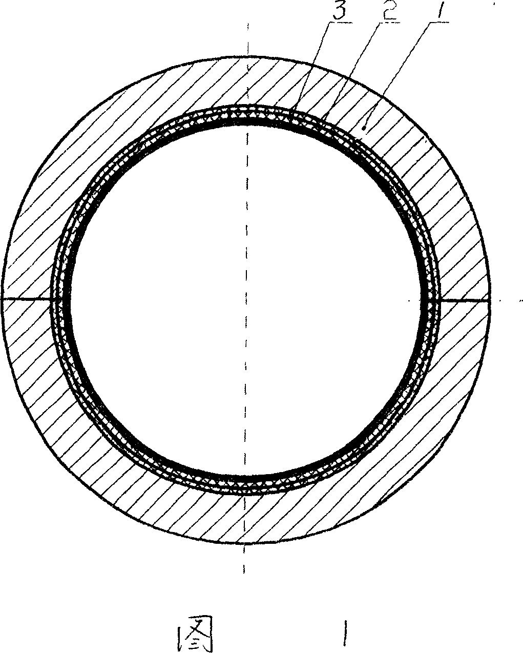
[0023] Embodiment 1 As shown in FIG. 1 , it is a cross-sectional view of a cylindrical bearing.
[0024] A. make tin bronze wire hole pad 2 according to prior art method;
[0025] b. Mix aramid fibers or carbon fibers with a weight percentage of 2 to 8, polyphenylene resin or polyimide with a weight percentage of 5 to 30, lead powder with a weight percentage of 5 to 25, and the remainder of polytetrafluoroethylene Evenly spread on the metal wire hole pad 2, molded and compounded into a blank according to the prior art method;
[0026] c. Sinter the blank to make a tile surface with a composite modified polytetrafluoroethylene plastic layer 3 embedded on the wire hole pad 2;
[0027] d. The tile surface is brazed on the steel tile base 1, and after mechanical finishing, the steel tile base 1 is firmly combined with the metal wire hole pad 2, and the metal wire hole pad 2 is embedded with composite modified PTFE Cartridge bearings with vinyl layer 3.
Embodiment 2
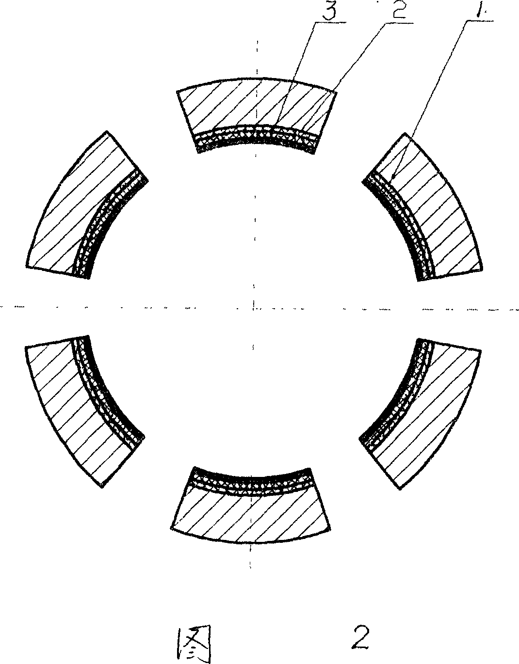
[0028] Embodiment 2 is shown in Figure 2, which is a cross-sectional view of a segmented bearing bush.
[0029] a. According to the method in the prior art, the tin bronze wire with a diameter of 0.2-0.8 mm is wound into a helical shape and cut into wire segments of 15-65 mm, and then molded to form the wire hole pad 2 .
[0030] b. Mix aramid fibers or carbon fibers with a weight percentage of 2 to 8, polyphenylene resin or polyimide with a weight percentage of 5 to 30, lead powder with a weight percentage of 5 to 25, and the remainder of polytetrafluoroethylene Evenly spread on the metal wire hole pad 2, molded and compounded into a blank according to the prior art method;
[0031] c. Sinter the blank to make a tile surface with a composite modified polytetrafluoroethylene plastic layer 3 embedded on the wire hole pad 2;
[0032] d. The tile surface is brazed on the sub-block steel tile base 1, and it is made by mechanical finishing. The steel tile base 1 is firmly combined...
Embodiment 3
[0034] a. According to the prior art method, steel wire and tin bronze wire with a diameter of 0.2 to 0.8 mm are respectively wound into a spiral shape and cut into a wire section of 15 to 65 mm; first the steel wire section is laid in the mold, and then Lay tin bronze wire section on it, the thickness ratio of steel wire section and tin bronze wire section is 1:1, makes metal wire hole pad 2.
[0035] b. Mix aramid fibers or carbon fibers with a weight percentage of 2 to 8, polyphenylene resin or polyimide with a weight percentage of 5 to 30, lead powder with a weight percentage of 5 to 25, and the remainder of polytetrafluoroethylene Evenly spread on the metal wire hole pad 2, molded and compounded into a blank according to the prior art method;
[0036] c. Sinter the blank to make a tile surface with a composite modified polytetrafluoroethylene plastic layer 3 embedded on the wire hole pad 2;
[0037] d. The tile surface is brazed on the steel tile base 1 as shown in Figur...
PUM
| Property | Measurement | Unit |
|---|---|---|
| Diameter | aaaaa | aaaaa |
Abstract
Description
Claims
Application Information
 - Generate Ideas
- Intellectual Property
- Life Sciences
- Materials
- Tech Scout
- Unparalleled Data Quality
- Higher Quality Content
- 60% Fewer Hallucinations
Browse by: Latest US Patents, China's latest patents, Technical Efficacy Thesaurus, Application Domain, Technology Topic, Popular Technical Reports.
© 2025 PatSnap. All rights reserved.Legal|Privacy policy|Modern Slavery Act Transparency Statement|Sitemap|About US| Contact US: help@patsnap.com