Sand/dust blowing environmental test equipment system

A technology of environmental test device and circulation device, which is applied in the direction of measuring device, aerodynamic test, machine/structural component test, etc., can solve the problem of sand and dust concentration, particle velocity and uniformity, sand and dust particle velocity and concentration The distribution is not easy to control, the pressure head of the main fan and the energy loss of the system increase, etc., to improve the dust concentration and speed distribution, improve the temperature control effect, and reduce the material and energy consumption.

Inactive Publication Date: 2007-11-14
BEIHANG UNIV
View PDF1 Cites 0 Cited by
  • Summary
  • Abstract
  • Description
  • Claims
  • Application Information

AI Technical Summary

Problems solved by technology

And because the air duct is designed as an open air duct (or wind tunnel), the loss of sand and dust material and the energy loss for temperature regulation during the test are relatively large; (2) when blowing dust, although the dust particles are small (grain diameter≤150μm), because the air duct is designed as a closed circulation air duct, the sand and dust material loss and energy loss during the test are reduced, but because the sand blowing and dust blowing tests use different test equipment, the test equipment Utilization rate is not high
Existing sand blowing and dust blowing environmental test equipment adopts the method of adding sand and dust by relying on gravity and the enveloping effect of the main air flow of the air duct. The test environment for dust concentration, particle velocity and uniformity before the specimen
Sand blowing and dust blowing tests need to strictly control the temperature and humidity in the environmental test equipment. If the existing temperature adjustment method of directly connecting the heat exchange surface and the electric heater into the sand blowing / dust blowing air duct is simply adopted, There will be a phenomenon that the pressure head of the main fan and the energy loss of the system will increase; in addition, because the adjustment object is a gas-solid two-phase flow containing sand and dust particles, it is impossible to use conventional drying methods to adjust its humidity

Method used


Image

  • Sand/dust blowing environmental test equipment system
  • Sand/dust blowing environmental test equipment system
  • Sand/dust blowing environmental test equipment system

Examples


Embodiment Construction

[0014] The present invention will be further described in detail below in conjunction with the accompanying drawings.

[0015] For sand blowing and dust blowing environment test equipment, it generally includes a sand and dust material system, a circulating air duct, and an air conditioning system. The required sand and dust raw materials; the air conditioning system is used to achieve the temperature and humidity of the test environment. The sand and dust material system and the air conditioning system are connected to the circulating air duct through pipelines. There are multiple valves on each pipeline. Humidity adjustment, humidity adjustment, etc.

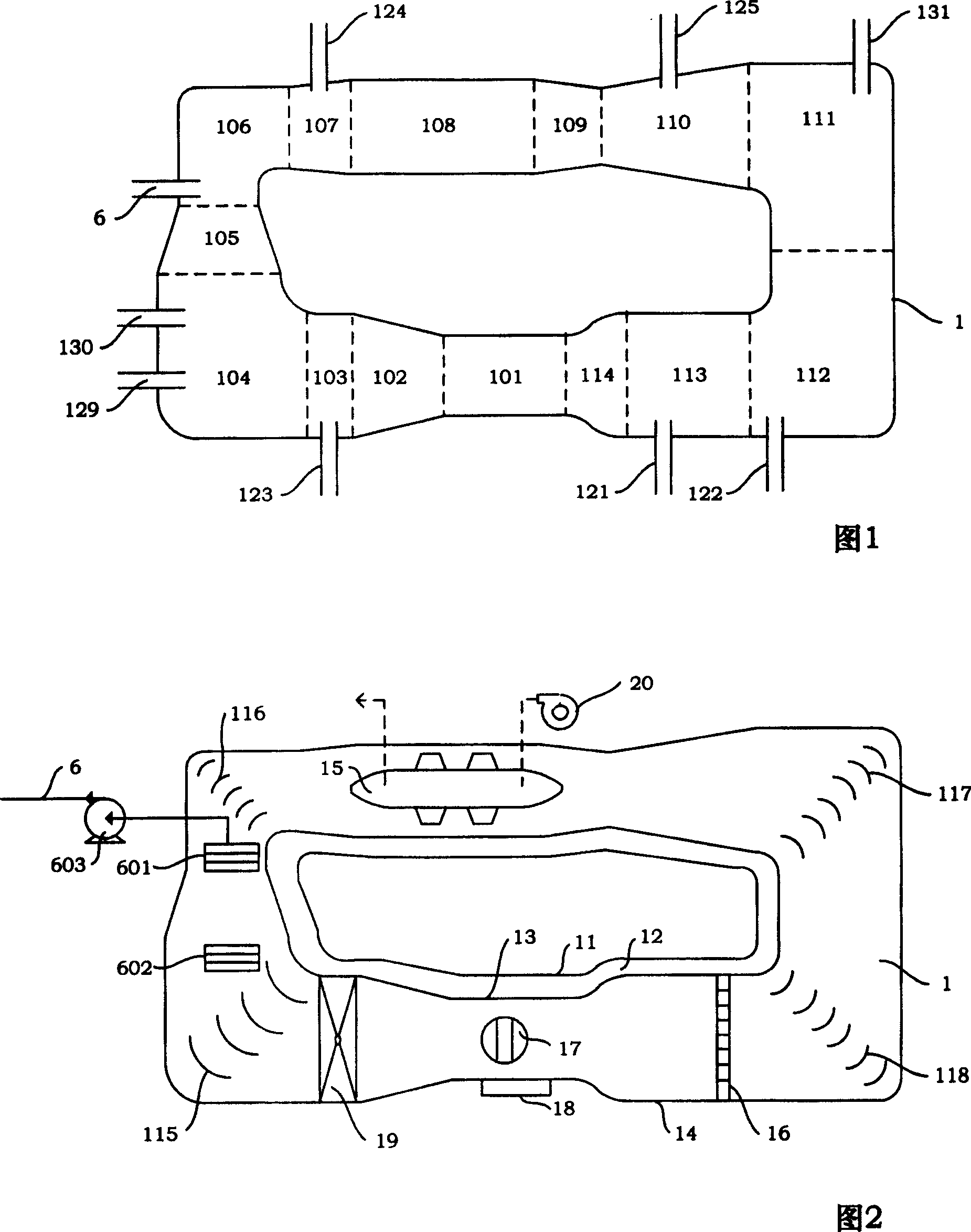
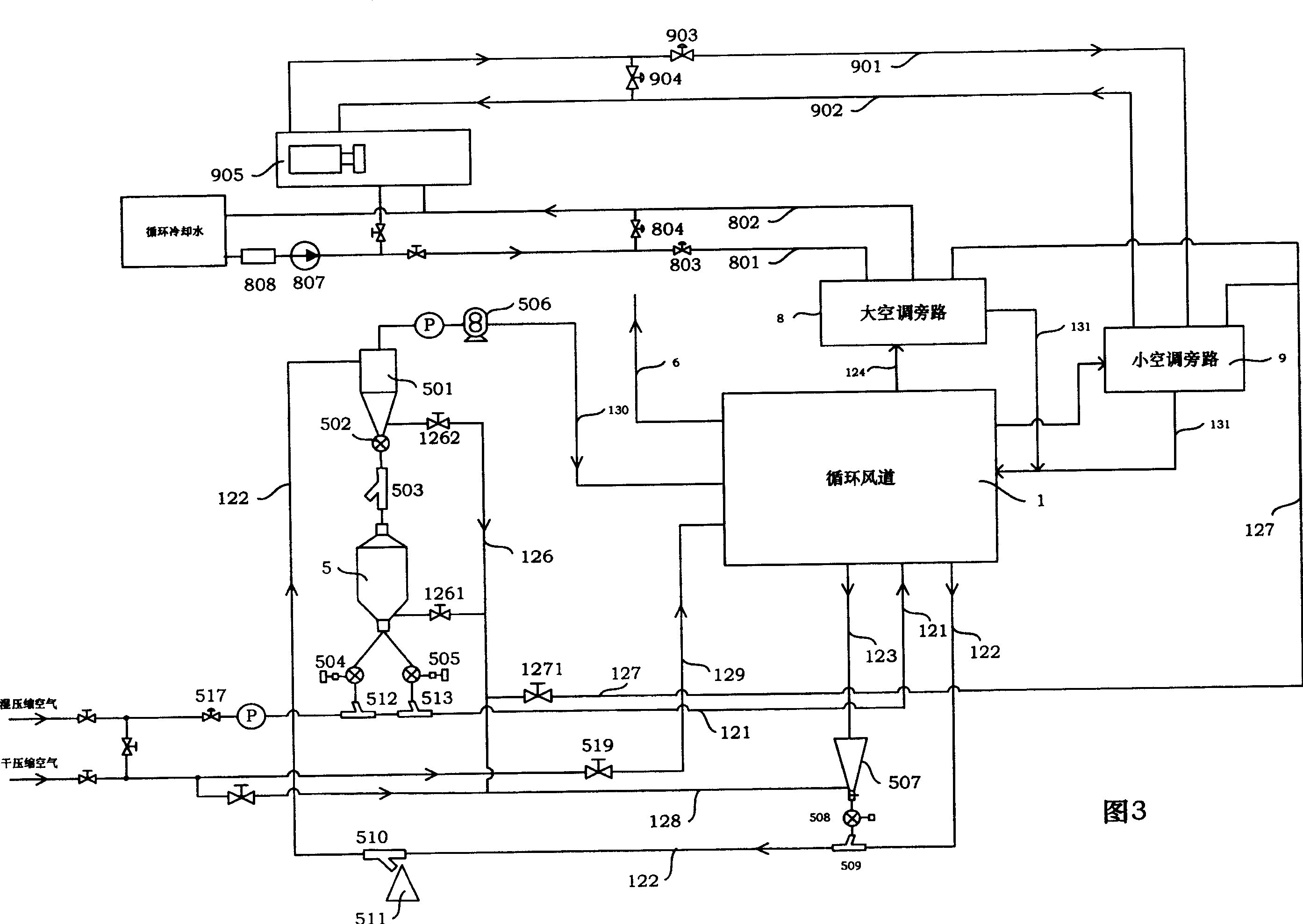
[0016] In the present invention, in order to realize gas-solid two-phase flow, structural improvements are made to the circulating air duct 1 . Circulating air duct 1 is a closed air duct with irregular structure. Circulating air duct 1 is divided into test section 101, diffuser section 102, separation section 103, first cor...


PUM


Abstract

The sand and dust environment test system includes circulating wind channel simulating wind speed environment, sand and dust material circulator, air regulator and pipe passages. The sand and dust material circulator and the air regulator are connected through the pipe passages to the circulating wind channel, and each of the pipe passages is equipped with valves for controlling flow rate, flow speed and pressure. The test air flows inside the circulating wind channel with fairing, heat insulating and air-solid separating functions and forms the required two phase air solid flow in the experiment section. The air regulator is used in regulating the temperature and humidity conditions in the experiment. The test system may be used in sand and dust environment experiment for vehicle, airplane, panzer and other large electromechanical equipment.

Description

technical field [0001] The invention relates to a device system capable of carrying out two environmental tests of sand blowing and dust blowing in the same set of equipment. Background technique [0002] Sand blowing and dust blowing tests are important means to test the environmental adaptability and environmental reliability of vehicles, aircraft, electrical equipment, and military equipment in deserts, arid areas, and windy sand weather conditions. [0003] At present, sand blowing and dust blowing tests need to be carried out in different environmental test equipment: (1) During sand blowing, due to the large sand and dust particles (with a particle size between 150 μm and 850 μm), the wear on the fan blades is relatively large. And because the air duct is designed as an open air duct (or wind tunnel), the loss of sand and dust material and the energy loss for temperature regulation during the test are relatively large; (2) when blowing dust, although the dust particles...

Claims


Application Information

Patent Timeline
Patent Type & Authority Patents(China)
IPC IPC(8): G01M19/00G01M9/00G01M99/00
Inventor 王浚李运泽董素君张华
Owner BEIHANG UNIV
Why Eureka
Try Eureka