
Automatic laser welding device for fibre-optical active component

A laser welding and active device technology, applied in laser welding equipment, welding equipment, metal processing equipment, etc., can solve the problems of poor device performance consistency, slow speed, low yield, etc., to eliminate angular deviation and have great flexibility , the effect of strong adaptability

Inactive Publication Date: 2007-11-28
NAT UNIV OF DEFENSE TECH
View PDF4 Cites 2 Cited by
  • Summary
  • Abstract
  • Description
  • Claims
  • Application Information

AI Technical Summary

Problems solved by technology

Due to the manual operation, it is particularly dependent on the proficiency of the operator, and it also has the disadvantages of slow speed, low output, low yield, poor device performance consistency, high product cost and price. At present, military and civilian fields are demanding high performance and low cost. The demand for optical fiber active devices is increasing, so it is necessary to develop an automatic laser welding device to complete automatic alignment and welding packaging on the submicron scale. Among them, the most critical technology lies in the alignment of high motion resolution mechanism

Method used


Image

  • Automatic laser welding device for fibre-optical active component
  • Automatic laser welding device for fibre-optical active component
  • Automatic laser welding device for fibre-optical active component

Examples


Embodiment Construction

[0070] The present invention will be described in further detail below in conjunction with the accompanying drawings and specific embodiments.

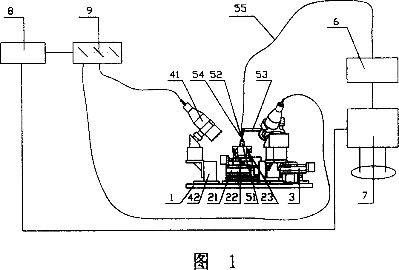
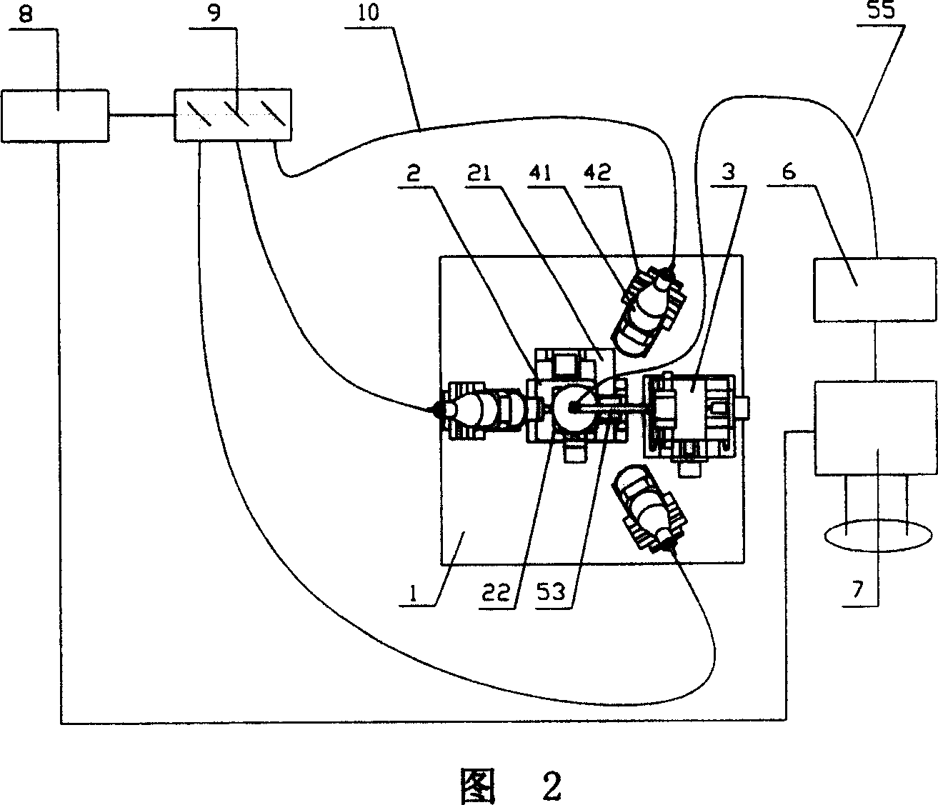
[0071] As shown in Figures 1 and 2, the automatic laser welding device for optical fiber active devices of the present invention includes a workbench 1, a control unit, a laser welding mechanism and a precision docking mechanism, and both the laser welding mechanism and the precision docking mechanism are installed on the workbench 1 . The precision docking mechanism includes a three-degree-of-freedom optical fiber position adjustment mechanism 3 and a four-degree-of-freedom light source device position adjustment mechanism 2. Relative position adjustment of five degrees of freedom of optical fiber. The laser welding mechanism includes a solid-state laser 8, a beam splitter 9, three identical transmission optical fibers 10, three identical focusing mirrors 41 and a focusing mirror adjustment mechanism 42, and the three focusing mirro...


PUM

PropertyMeasurementUnit
angle of incidenceaaaaaaaaaa

Abstract

The automatic laser welding apparatus for active fiber device includes a work table, a control unit, a laser welding mechanism and a precise butt jointing mechanism, and the laser welding mechanism and the precise butt jointing mechanism are installed on the work table. The precise butt jointing mechanism includes a fiber position regulating mechanism and a light source device position regulating mechanism, the fiber position regulating mechanism includes three successively superposed 1D translation stages and one fiber device fixture on the stages, and the light source device position regulating mechanism includes one 2D inclined stage and two orthogonal micro platforms in the same structure and on the inclined stage. The control unit includes one host control computer and one light power meter and is connected via cables to other mechanisms. The present invention has the advantages of simple structure, simple control, low cost, great stroke, high resolution, etc.

Description

technical field [0001] The invention mainly relates to the submicron manufacturing theory and key technical fields of optical fiber devices, in particular to an automatic laser welding device for optical fiber active devices. Background technique [0002] In the prior art, optical fiber active devices include components and modules of various optoelectronic devices such as light sources (LD, LED), detectors, optical amplifiers, light source-fiber couplers, and light source-detection couplers. Optical fiber active components are the core of the optical fiber application system, which not only affects the performance of the system, but also has a great impact on the cost of the entire system. How to couple light from the light source into the optical fiber to obtain high coupling efficiency is a key issue in the packaging of optical fiber active devices. The core technology is to achieve sub-micron alignment and welding. [0003] At present, the alignment in the packaging of...

Claims


Application Information

Patent Timeline
Patent Type & Authority Patents(China)
IPC IPC(8): B23K26/02B23K26/20B23K26/08B23K26/21B23K26/70
Inventor 李圣怡吴宇列戴一帆淳静张爱成
Owner NAT UNIV OF DEFENSE TECH
Learn More