Excess temperature protector for driving motor of electric automobile

A technology for driving motors and electric vehicles. It is applied in the direction of emergency protection circuit devices and electrical components. It can solve the problems of motor overheating, limited temperature points for detection, and difficult temperature detection, so as to improve reliability, accurately judge, and prevent The effect of overheating damage

A technology for driving motors and electric vehicles. It is applied in the direction of emergency protection circuit devices and electrical components. It can solve the problems of motor overheating, limited temperature points for detection, and difficult temperature detection, so as to improve reliability, accurately judge, and prevent The effect of overheating damage

CN100353633CInactive Publication Date: 2007-12-05北京京工大洋电机科技有限公司

Image

  • Excess temperature protector for driving motor of electric automobile

Examples


Embodiment 1

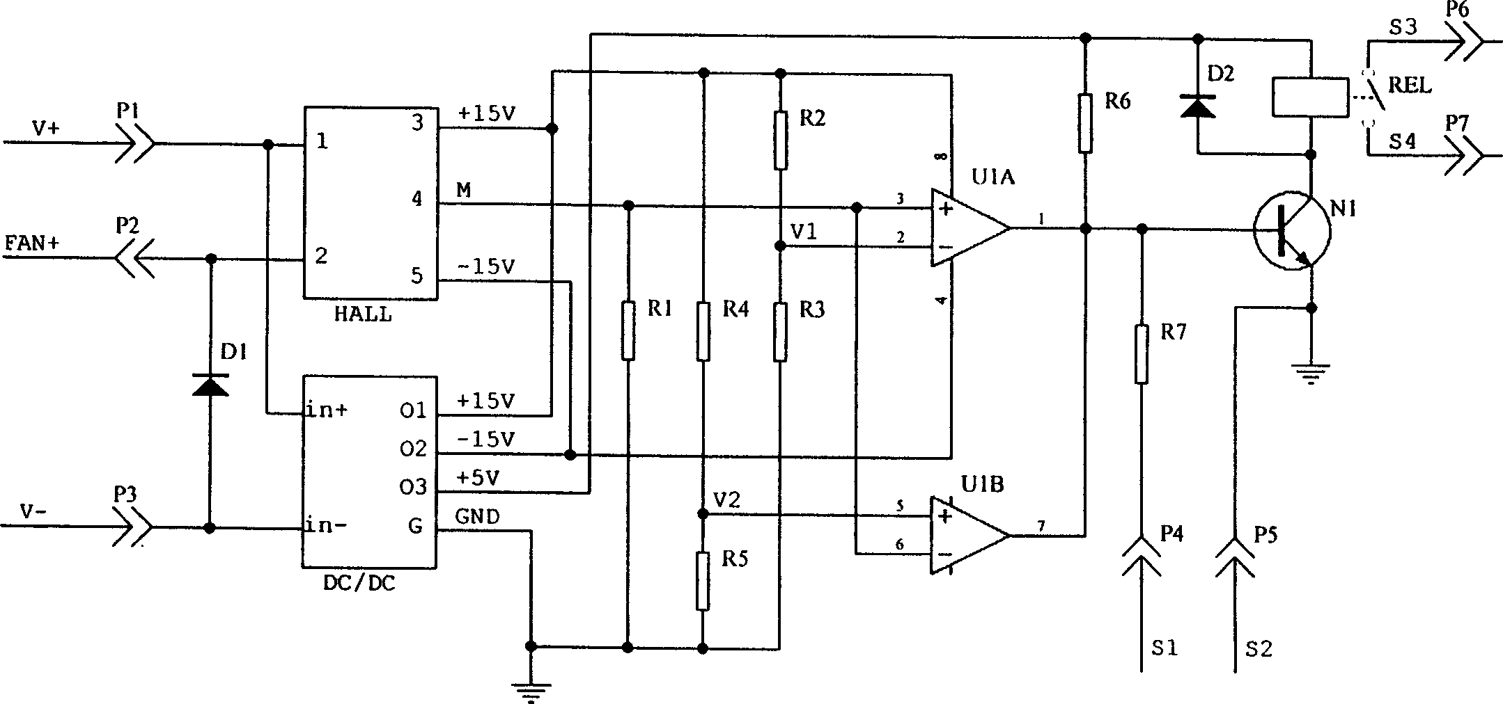
[0009] In the circuit shown in the attached figure, for a drive motor over-temperature protector of an air-cooled DC motor drive system used in an electric bus, the low-voltage DC power supply on the vehicle is 24V, and the DC / DC converter DC / DC selects the model It is the power module of WR24S5D15, the Hall current sensor HALL is a Q20A-10mA magnetic balance sensor, R1 is 2K, U1A and U1B are two comparators on the LM2903 integrated comparator, due to the normal operating current lower limit of the driving motor cooling fan The value and upper limit are 6A and 10.2A respectively, the corresponding R2, R3, R4 and R5 values ​​are 3K, 2K, 2.4K and 5.1K respectively, the obtained undercurrent reference voltage V1 is 6V, overcurrent The reference voltage V2 is 10.2V, R6 is 5.1K, the relay REL model is NT90RHC-SDC24, the transistor N1 model is BD237, D1 selects 3A / 100V diode, D2 selects 1A / 100V diode, the thermal relay installed on the drive motor outside the protector It is a norma...


PUM


Abstract

The invention is an electric auto driving motor cooling fun protector, according to the working current range, determining if the cooling fan works normally: if it is abnormal, send trouble information to an motor controller, which can stop the driving motor working or reduce output power of the driving motor, thus preventing overtemperature damage, even destruction to the driving motor caused by the abnormal working of the cooling fan, and the invention can be used not only in protecting electric auto driving motor but also in protecting other driving motors in need of cooling fans.

Description

technical field [0001] The invention relates to an over-temperature protector for a drive motor of an electric vehicle, in particular to an over-temperature protector for an external air-cooled drive motor of an electric vehicle. Background technique [0002] There are two cooling methods for the air-cooled electric vehicle drive motor. One is self-air cooling. The cooling fan in this air-cooling method is installed on the shaft of the drive motor, and the fan blades of the fan rotate as the rotor of the drive motor rotates. Rotation, the speed is the same as the motor rotor speed, the other is the external air cooling method, the cooling fan of this method is generally powered by the 24V or 12V DC low-voltage power supply on the vehicle, which overcomes the self-air cooling method. The disadvantage of poor cooling effect is widely used. For the over-temperature protection of the drive motor of the external air-cooled electric vehicle, the current technology mainly adopts th...

Claims


Application Information

Patent Timeline
05 Dec 2007
Publication
CN100353633C
IPC
H02H7/08
Inventors
孙逢春; 张承宁