Omnibearing self-aligning method for detector-optical fiber coupling

A technology of optical fiber coupling and detectors, which is applied in the direction of instruments, using optical devices to transmit sensing components, etc., can solve the problems of inability to realize automatic and accurate positioning, high requirements for operating environment and production technology, and high instability, so as to improve the disposable Success rate, save human resource costs, and improve labor productivity

Inactive Publication Date: 2008-03-05
UNIV OF ELECTRONICS SCI & TECH OF CHINA
View PDF6 Cites 0 Cited by
  • Summary
  • Abstract
  • Description
  • Claims
  • Application Information

AI Technical Summary

Problems solved by technology

This is a time consuming and costly process, and any small deviation of the core relative to the photodetector active area during curing and after packaging introduces significant coupling losses
In short, in addition to the problem of low coupling efficiency, the existing technologies and methods also have the following disadvantages: 1) The manufacturing process is complicated, and the requirements for equipment are relatively high, and they will encounter great problems when they are applied in actual production. obstacles
2) High requirements on the operating environment and production technology, resulting in high instability when put into production
3) There are still many steps in the production process, and there is a bottleneck in improving the one-time production pass rate of the product
However, although Indian scholars proposed the self-alignment (self-alignment) concept, they only used a conventional wet chemical etching process. Insert the optical fiber 3 in the direction of the ridge to achieve one-dimensional self-alignment, but cannot achieve all-round automatic and precise positioning, as shown in Figure 1

Method used


Image

  • Omnibearing self-aligning method for detector-optical fiber coupling
  • Omnibearing self-aligning method for detector-optical fiber coupling

Examples


Embodiment Construction

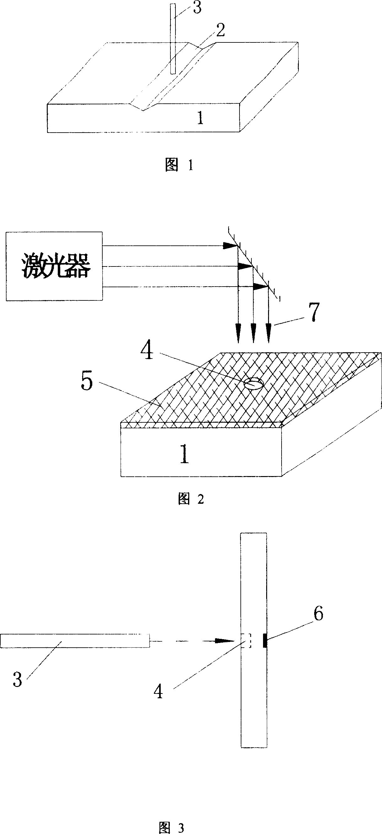
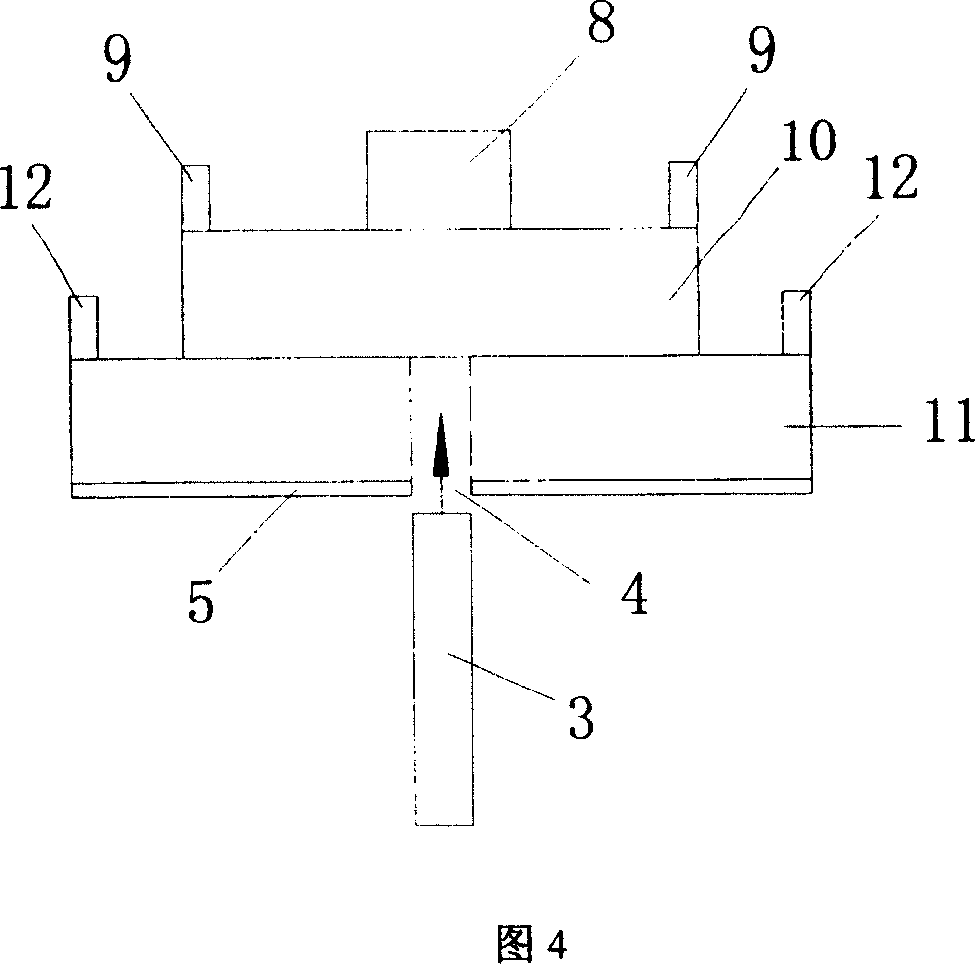
[0038] Realize the detector-fiber omnidirectional self-alignment coupling of InP substrate photodetector with pigtail (as shown in Figure 4)

[0039] Step 1 Prepare the semiconductor InP substrate, and determine the P + The location of the diffusion region 8, the front side of the semiconductor substrate P + The position of the diffusion region 8 corresponds to the InP backside N of the semiconductor substrate + The position of the diffusion area 11 is exactly the position of the corroded circular hole 4, i.e. the position where the light of the back optical fiber 3 is incident; The diameter of the optical fiber 3 is subject to the fact that the optical fiber 3 is inserted into the corroded hole 4 and does not shift; the depth of the hole of the corroded hole 4 is subject to the fact that the optical fiber 3 is inserted into the corroded hole 4 and does not fall off, as shown in Figure 4;

[0040] Step 2 Use the resist film 5 to cover the back surface of the semiconductor su...


PUM


Abstract

A method for coupling detector on optical fiber in omni bearing self alignment way includes utilizing laser auxiliary corrosion technique to generate corrosion hole on back surface of semiconductor substrate for preparing round hole detector, inserting optical fiber in round hole for aligning optical fiber to front photosensitive surface of detector accurately so as to realize nonbearing self alignment couple of detector - optical fiber.

Description

Technical field: [0001] The invention belongs to the technical field of optoelectronics, and particularly relates to the technical field of realizing detector-fiber coupling. Background technique: [0002] Detector-fiber coupling technology is the key technology for making detectors with pigtails. The purpose is to achieve precise coupling between the detector and the fiber, improve its coupling efficiency, and thus improve the overall performance of the detector. [0003] Due to its unique advantages in capacity and anti-interference ability, optical fiber systems have been or will be widely used in communications, aerospace, ultra-high-speed computers and other fields. In the optical fiber system, since the photosensitive surface of the detector and the cross section of the optical fiber core are very small (10 microns or even microns), it is very difficult to precisely align and cure each other. The good coupling between the detector and the fiber and its low-cost fabric...

Claims


Application Information

Patent Timeline
Patent Type & Authority Patents(China)
IPC IPC(8): G01D5/26G01D18/00
Inventor 叶玉堂刘霖吴云峰赵素英杨先明范超王昱琳
Owner UNIV OF ELECTRONICS SCI & TECH OF CHINA
Why Eureka
Try Eureka