
Method for measuring parallel beam injection angle

A technology of injection angle and measurement method, applied in the field of parallel beam injection angle measurement, to achieve the effects of easy operation, accurate measurement and simple method

Active Publication Date: 2008-04-02
BEIJING SHUOKE ZHONGKEXIN ELECTRONICS EQUIP CO LTD
View PDF5 Cites 0 Cited by
  • Summary
  • Abstract
  • Description
  • Claims
  • Application Information

AI Technical Summary

Problems solved by technology

[0004] The present invention aims at the situation that it is difficult to accurately measure the injection angle of parallel beams in the prior art, and proposes a new measurement method, which is simple, practical and accurate

Method used


Image

  • Method for measuring parallel beam injection angle

Examples


Embodiment Construction

[0014] The present invention is described in further detail below in conjunction with specific embodiment:

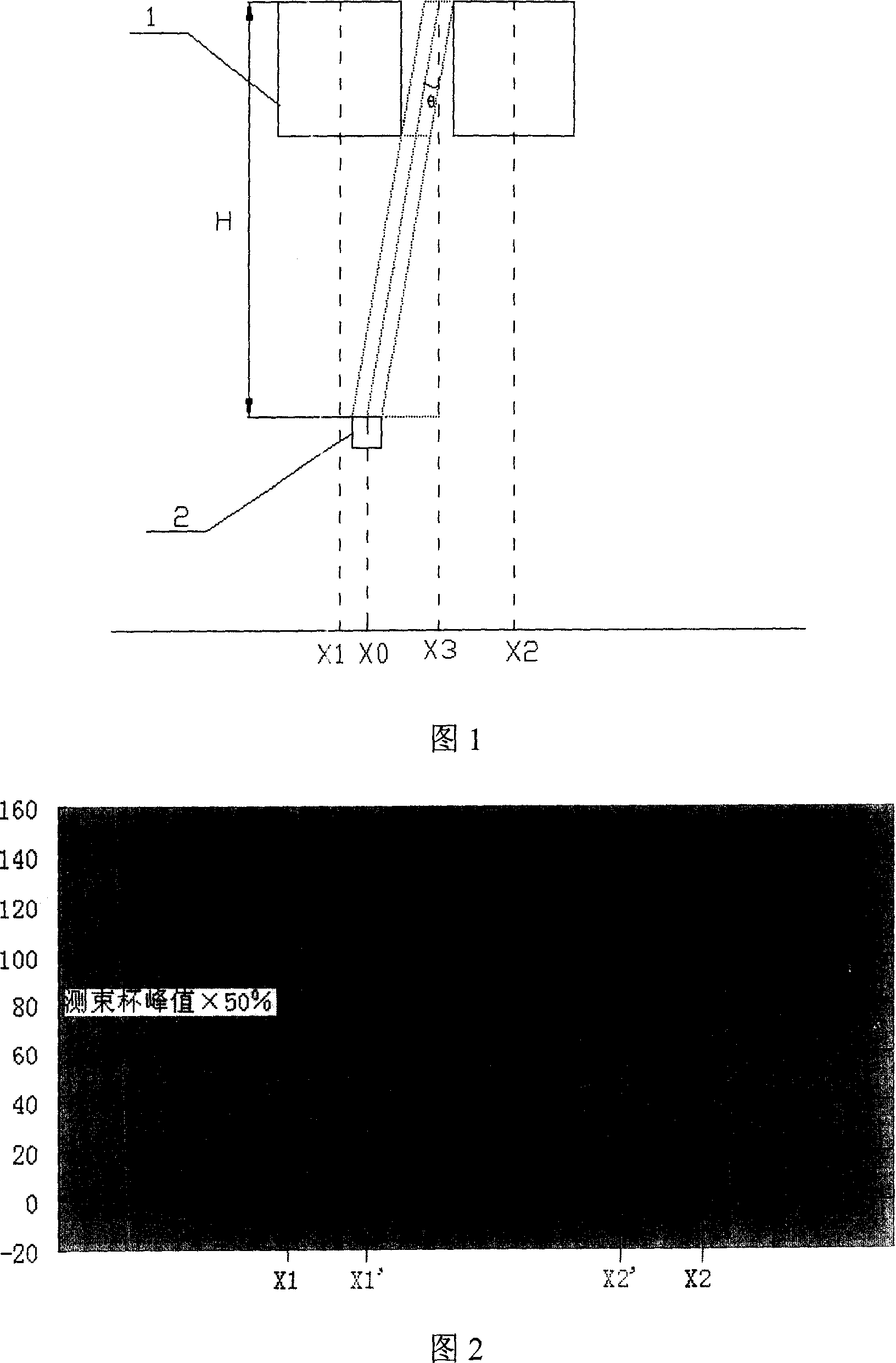
[0015] As shown in Figure 1, after the ion beam is swept away by the scanning power supply, it comes out of the parallel beam lens and the accelerating field and is injected into the wafer. One or more measuring beam Faraday 2s are set at the wafer position, and the Faraday 1 beams are moved from left to right. Move to the right, according to the parallel beam angle measurement formula, the parallel beam injection angle at the Faraday position of the measuring beam can be measured.

[0016] Parallel beam angle measurement formula:

[0017] As shown in Figure 1, the moving Faraday 1 moves from left to right. When the moving Faraday 1 moves to the position X1, the beam current measured by the measuring beam Faraday 2 begins to decrease. When the moving Faraday 1 moves to the position X2, the measuring beam Faraday 2 The measured beam current returns to its maximum value....


PUM


Abstract

This invention discloses parallel beam injection angle measuring method. Moving faraday and beam faraday are used. The procedures are that (1) the moving faraday method is used to shelter ion beam to make the beam faraday method forming corresponding current curve graph. (2) parallel beam injection angle is computed by formula theta=arctg((X1'+X2') / 2-X0) / (H-h / 2), X1', X2'are 50 percent two points position of beam measuring cup current peak value, X0 is midpoint position of the cup, h is moving faraday height, H is distant between the moving faraday and beam faraday. This invention is simple and practical, its operation is easy and measuring is accurate.

Description

technical field [0001] The invention relates to a semiconductor device manufacturing control measurement method, in particular to a parallel beam injection angle measurement method. Background technique [0002] In the existing semiconductor integrated circuit manufacturing technology, with the development of semiconductor integrated circuit technology, the integration level is getting higher and higher, and the foundry wafer size is getting larger and larger, from 6 inches to 8 inches, or even 12 inches, the unit in the circuit The size of devices is getting smaller and smaller, which puts forward higher requirements for the automation of various semiconductor process equipment. [0003] As one of the key equipment of the semiconductor ion doping process line, the ion implanter also puts forward higher requirements. When the wafer size of the foundry reaches 8 inches or 12 inches, the ion implanter is required to have: good reliability of the whole machine, Precise control...

Claims


Application Information

Patent Timeline
Patent Type & Authority Patents(China)
IPC IPC(8): H01L21/00H01L21/265H01L21/66C23C14/48H01J37/317
Inventor 唐景庭罗宏洋孙勇谢均宇
Owner BEIJING SHUOKE ZHONGKEXIN ELECTRONICS EQUIP CO LTD
Learn More