Replacing method of valv device, processing system and sealing components

A technology for sealing parts and gate valves, applied in valve devices, lift valves, sliding valves, etc., can solve the problems of prolonging the vacuuming time, reducing production capacity, and reducing the utilization rate of devices, and achieving the effect of improving safety.

Active Publication Date: 2008-04-23
TOKYO ELECTRON LTD
View PDF7 Cites 0 Cited by
  • Summary
  • Abstract
  • Description
  • Claims
  • Application Information

AI Technical Summary

Problems solved by technology

Among them, at this time, other processing chambers are closed by other gate valve devices. In this case, after the maintenance operation is completed or the sealing parts are replaced, although it is possible to evacuate the transfer chamber and the processing chamber respectively and return to the The specified decompression atmosphere, but once it is opened to the atmosphere, since the moisture and impure gas in the air will adhere to the inner wall surface, in order to remove the adhered moisture and impure gas, it is necessary to extend the vacuum. time, which will cause a decline in device utilization and production capacity

Method used


Image

  • Replacing method of valv device, processing system and sealing components
  • Replacing method of valv device, processing system and sealing components
  • Replacing method of valv device, processing system and sealing components

Examples


no. 1 example

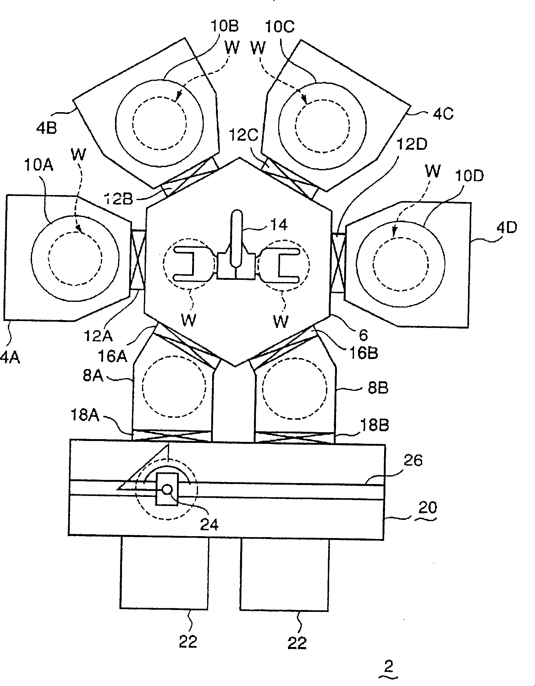
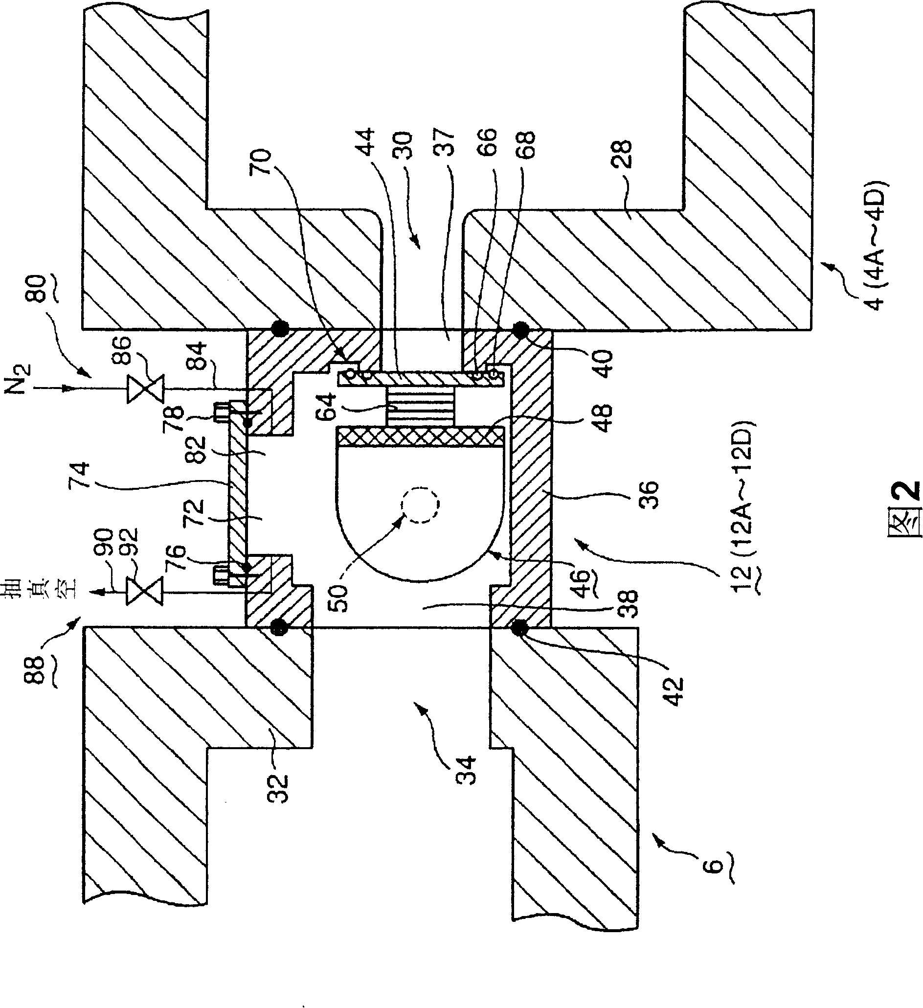
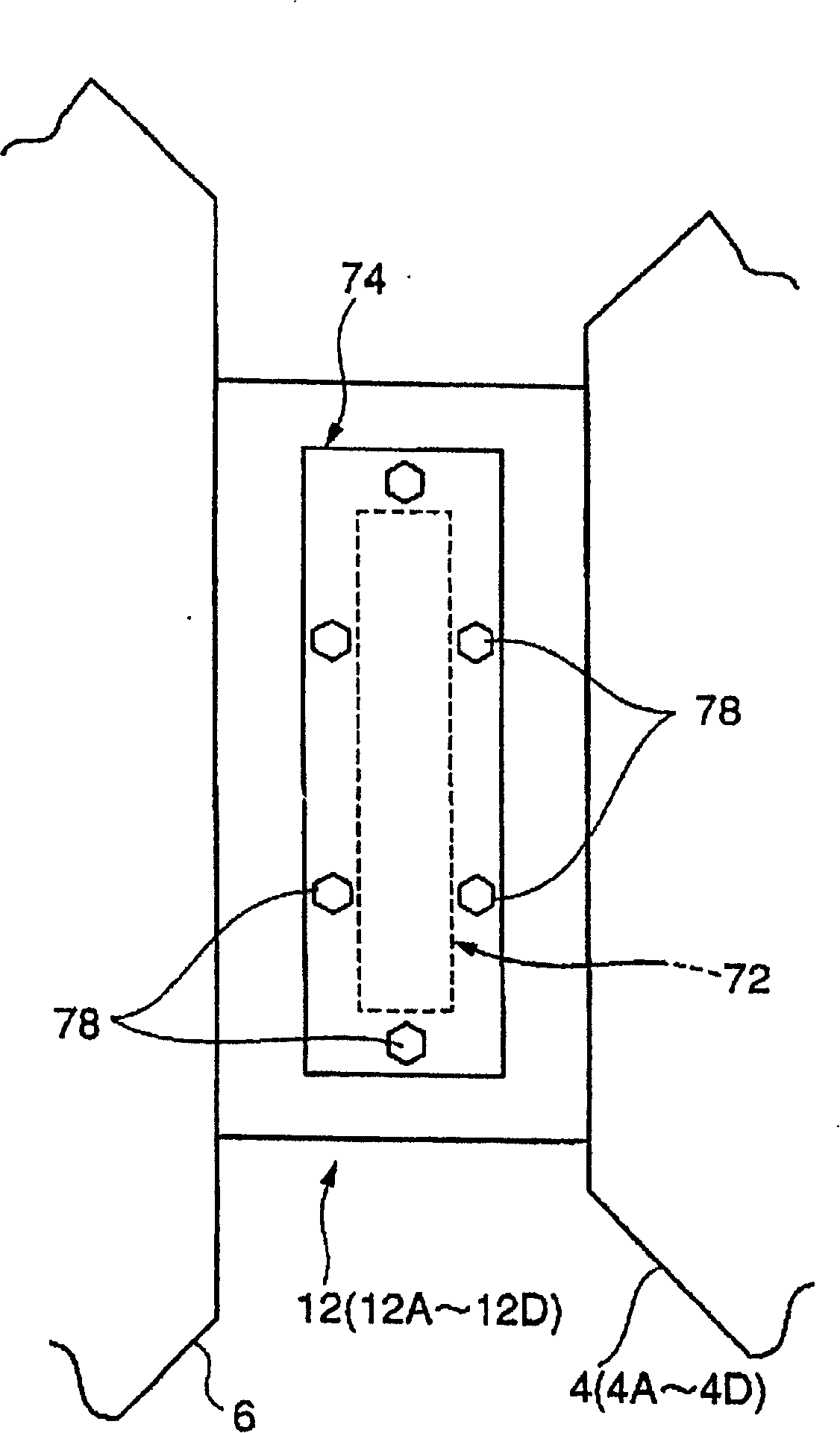
[0078] figure 1 It is a plan view showing an example of a processing system using the gate valve device of the present invention; FIG. 2 is an enlarged cross-sectional view showing the installation state of the first embodiment of the gate valve device of the present invention; image 3 It is the top view (top view) of the gate valve device; Figure 4 It is a perspective view showing the installation state of the valve body and the valve body drive mechanism from the front; Figure 5 It is a perspective view showing the installed state of the valve body and the valve body driving mechanism from the rear; FIG. 6 is an action explanatory diagram for explaining the action of the first embodiment of the gate valve device; Figure 7 It is a process chart showing the flow of seal member replacement.

[0079] Such as figure 1 As shown, the processing system 2 mainly includes: a plurality of (for example, 4) processing chambers 4A, 4B, 4C, 4D, a common hexagonal transfer chamber 6 ...

no. 2 example

[0112] Next, a second embodiment of the gate valve device of the present invention will be described.

[0113] Fig. 8 is an operation explanatory diagram for explaining the operation of the second embodiment of the gate valve device of the present invention. However, the same components as those shown in FIG. 6 are denoted by the same reference numerals, and description thereof will be omitted. In addition, in FIG. 8, only the main part of a gate valve device is shown.

[0114] In the case of the above-mentioned first embodiment, the recessed contact avoiding step 70 is formed on the mounting surface of the loading and unloading port 37 to avoid contact with the sealing member 68 for maintenance when the valve body 44 is assembled. In the second embodiment, the contact-avoiding stepped portion 70 is provided on the surface peripheral portion of the valve body 44 . Wherein, other structures are the same as those of the first embodiment. Specifically, the valve body 44 is for...

no. 3 example

[0117] Next, a third embodiment of the gate valve device of the present invention will be described.

[0118] Figure 9 is a sectional view showing a third embodiment of the gate valve device of the present invention. However, the same components as those described above are denoted by the same reference numerals, and description thereof will be omitted. In addition, in Figure 9 Only the main part of the gate valve device is indicated in .

[0119] In the above-mentioned first and second embodiments, the valve body supporting member 48 of the valve body driving mechanism 46 is rotatable, but in the third embodiment, the valve body supporting member 98 is formed in a rod shape, and can be moved up and down. The structure of the direction of movement. Further, a valve body 44 capable of advancing and retreating is provided at the front end portion of the valve body supporting member 98 . Furthermore, the frame body 36 is extended upward to form a rectangular cross-section,...


PUM


Abstract

The invention provides a door valve device which can still replace a sealing component without providing a handling room to atmosphere. A door valve device (12) which is installed between a handling opening of a treatment chamber (4), and a handling room (6) in open-close and vacuum states comprises a valve body (44) which can be assembled through opening-closing the handling opening; a sealing component (66) which can be installed on the surface of the valve body in a assembly and disassembly way and is hermetically contacted with the assembly surfaces around the handling opening; a sealing component (68) used for maintenance and encircled on the periphery of the sealing component through the regulated interval to the sealing component; an opening (72) used for maintenance; an opening-closing cover (74) used for detachably and hermetically blocking the outer side of the opening used for maintenance and used for maintenance; a valve body driving mechanism (46) which is installed in order to ensure the valve body to be moved between the handling opening and the opening used for maintenance, wherein when the valve body is assembled, and in the state that the sealing component is exposed, the opening (72) used for maintenance becomes the size that the sealing component used for maintenance can be hermetically sealed.

Description

technical field [0001] The present invention relates to a gate valve device used in a processing chamber for performing predetermined processing on a target object such as a semiconductor wafer, a processing system having a plurality of such processing chambers, and a method for replacing a sealing member of the gate valve device. Background technique [0002] Generally, in the manufacturing process of a semiconductor device, various processes such as dry etching, sputtering, CVD (Chemical Vapor Deposition) and the like are repeatedly performed on a semiconductor wafer. The above-mentioned various processes are often carried out in a vacuum atmosphere, and the loading opening for loading and unloading wafers into the processing chamber where such processing is performed is highly airtightly sealed by a gate valve during the processing. [0003] Such a gate valve device is disclosed in, for example, Patent Document 1 or the like. For example, a carry-in opening of a size and...

Claims


Application Information

Patent Timeline
Patent Type & Authority Patents(China)
IPC IPC(8): H01L21/00H01L21/02H01L21/20H01L21/203H01L21/205H01L21/3065H01L21/677C23C16/44C23C14/22C23F4/00F16K51/02
CPCF16K51/02H01L21/67126F16K1/24F16K3/04F16K3/28H01L21/67772
Inventor 广木勤
Owner TOKYO ELECTRON LTD
Why Eureka
Try Eureka