Small high-power relay

A high-power relay, small-scale technology, applied in the direction of relays, electromagnetic relays, detailed information of electromagnetic relays, etc., can solve the problems of leakage of sealing materials into relays, reduction of withstand voltage of contacts and coils, reduction of creepage distance, etc., to achieve reliability Improvement, the number of ampere-turns increases, and the effect of increasing the creepage distance

Active Publication Date: 2008-05-07
NINGBO FORWARD RELAY CORP
View PDF2 Cites 0 Cited by
  • Summary
  • Abstract
  • Description
  • Claims
  • Application Information

AI Technical Summary

Problems solved by technology

However, by analyzing the relay of this structure, we can find that, in the case of determining the pin position, in order to facilitate the contact system process installation requirements, the hole of the base through which the reed needs to pass must be exposed, and this makes the base contain the magnetic circuit system The depth of the cavity is relatively reduced. When the rated voltage is fixed, the length of the coil frame of the magnetic circuit system will be reduced, and the diameter of the coil will be increased. In the case of the same external volume, the base contains the magnetic circuit system. The thickness of the cavity will be correspondingly thinner, and its technical effect is to reduce the creepage distance and the withstand voltage between the contact and the coil; in addition, during the installation process of the product, the installation of the contact system and the magnetic circuit system Both are cumbersome, and the work efficiency is relatively low. After the magnetic circuit system is installed, the groove for setting the coil lead piece needs to be sealed with a corresponding sealing material. If the operation is improper, the sealing material will leak into the interior of the relay.

Method used


Image

  • Small high-power relay
  • Small high-power relay
  • Small high-power relay

Examples


Embodiment 1

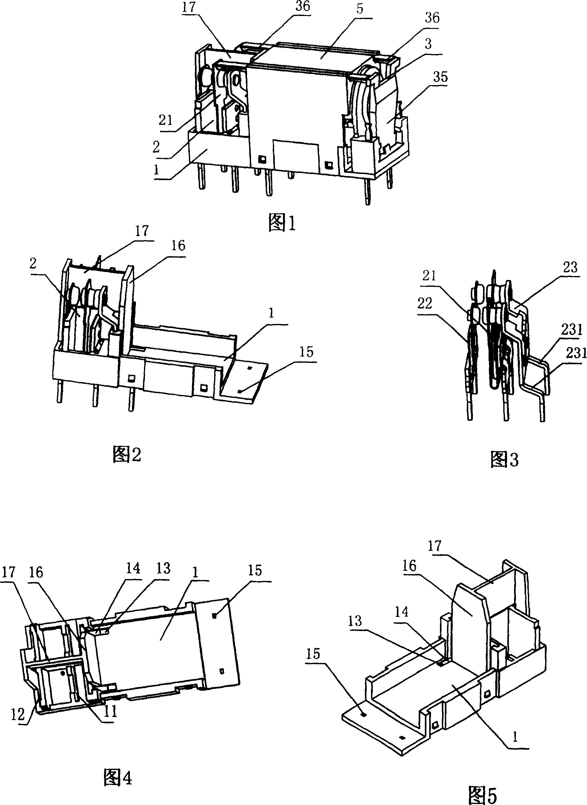
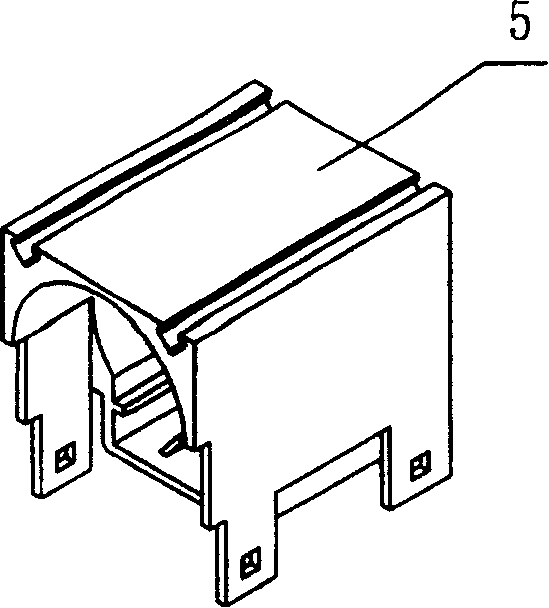
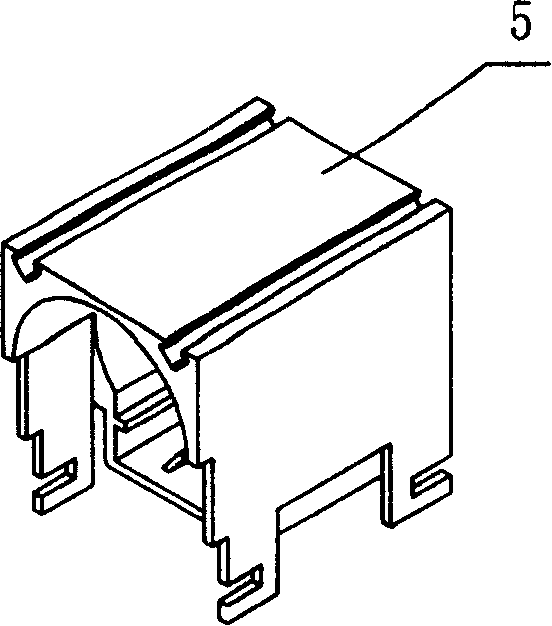
[0026] Embodiment 1: A small high-power relay, including a base 1, a contact system 2, a magnetic circuit system 3 and a case 4, and the contact system 2 includes a moving contact piece 21, a normally open static contact piece 22 and a normally closed static contact piece 23 , the base 1 is correspondingly provided with a moving contact jack 11, a normally open static contact jack 12 and a normally closed static contact jack 13, and the magnetic circuit system 3 includes a coil 31, a lead piece 32, an iron core 33, and a yoke 34 And the armature 35, the armature 35 is connected with the moving contact piece 21 through the push rod 36, the magnetic circuit system 3 is provided with an insulating cover 5, the combination of the coil 31 and the yoke 34 is arranged in the insulating cover 5, and the normally closed static contact piece jack 13 is provided with a contact groove 14 extending along the upper bottom surface of the base 1, the lower part of the normally closed static co...

Embodiment 2

[0027] Embodiment 2: Other structures are the same as Embodiment 1, except that the contact system 2 includes a set of changeover contacts, and the insulating partition 16 is not provided with a vertical and integrally connected auxiliary insulating partition.


PUM


Abstract

This invention discloses a small large power relay including a base, a contact system, a magnetic circuit system and a casing among which, the contact system includes a dynamic contact plate, a normal open static contact plate and a normal close static contact plate, a dynamic contact plate plug hole, a normal open static contact plate hole and a normal close static contact plate hole are set on the base, the magnetic circuit system includes a coil, a lead plate, an iron core, a yoke and an armature characterizing that an insulating boot is set on the magnetic circuit, a contact plate slot extending along the upper base surface of the base is set beside the static contact plate hole, a bending part is set at the lower part of the close static contact plate and inserted in the contact plate slot, the boot is set above the plug hole of the static plate and the slot and connected with the base having a lead plate plug hole with the lead plate plugged in it, which increases the creep distance and enhances the voltage endurance between the contact point and the coil.

Description

technical field [0001] The invention relates to a relay, in particular to a small high-power relay. Background technique [0002] Existing small high-power relays are mainly used in household appliances, automation systems, electronic equipment, instruments and meters, communication devices and remote control devices. The withstand voltage between the coil and the coil is as high as possible. For example, the No. 01220748.9 utility model patent authorized by the announcement on January 16, 2002 discloses a small, high-power, sensitive DC electromagnetic relay with ultra-low height, which is mainly composed of a contact system, a magnetic circuit system, a base and a housing. The contact system includes a static The reed and the U-shaped moving reed are inserted into the base through the guide groove on the base, and the U-shaped bending part of the moving reed is inserted into the guide groove of the base to fix. The relay with this structure has a lower height, a larger c...

Claims


Application Information

Patent Timeline
Patent Type & Authority Patents(China)
IPC IPC(8): H01H50/16H01H50/54H01H50/14
Inventor 杨晓厦余正海
Owner NINGBO FORWARD RELAY CORP
Why Eureka
Try Eureka