

Flow structure of controlling liquid continuously flowing in micro-pipeline
A micro-pipeline and liquid technology, applied in gas/liquid distribution and storage, pipeline systems, mechanical equipment, etc., to achieve the effect of convenient bubble-free fusion and reliable effect
- Summary
- Abstract
- Description
- Claims
- Application Information
AI Technical Summary
Problems solved by technology
Method used
Image

Examples
Embodiment 1
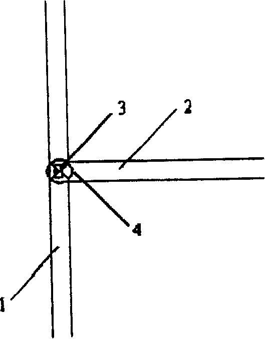
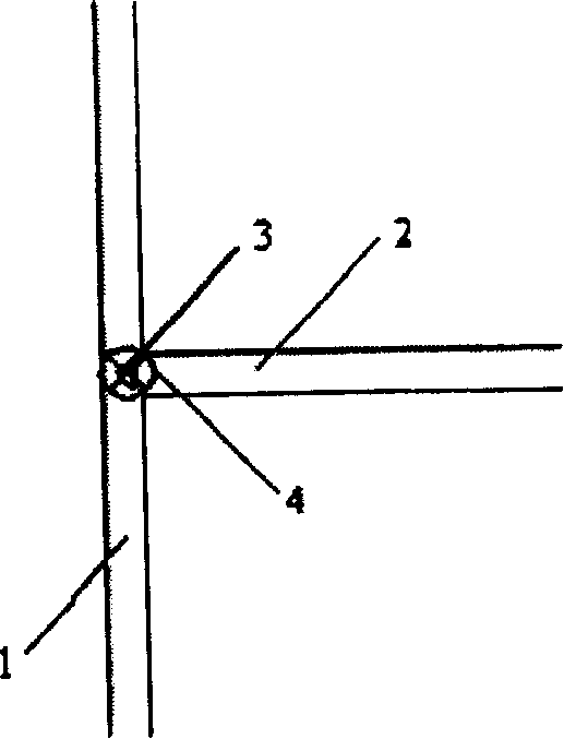
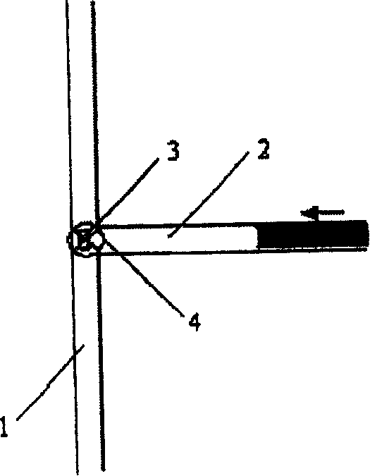
[0024] Such as figure 1 Shown, the structure of the present invention comprises a main micropipe 1, an auxiliary micropipe 2 communicated with the main micropipe 1, and a bluff body 3 is set at the confluence area of the auxiliary micropipe 2 and the main micropipe 1, which can effectively To reduce the area of the flow path, the shape of the bluff body 3 can be a rectangle or a triangle (such as figure 2 shown), other shapes are also possible. The inlet ends of the main micropipe 1 and the auxiliary micropipe 2 are respectively provided with a driving device (not shown in the figure) that provides a driving force. The driving force generated by the device. Such as figure 1 As shown, a sensor 4 can also be arranged in the confluence area for monitoring the inflow and outflow of liquid.
[0025] The fabrication of the above-mentioned structure can adopt the usual method of making chips. First, the grooves forming the micropipes 1 and 2 and the baffle body 3 are made on...
Embodiment 2
[0040] Such as Figure 8 As shown, this embodiment includes a main micropipe 1 and an auxiliary micropipe 2 , and when the auxiliary micropipe 2 approaches the confluence area with the main micropipe 1 , it branches to form a bypass micropipe 5 . Auxiliary micropipe 2 and main micropipe 1 form a confluence region a at point a, and a bluff body 3 is set in confluence region a; bypass micropipe 5 and main micropipe 1 form another confluence region b at point b, and A bluff body 3 ′ is arranged in the confluence region b, and after the two liquids merge in the confluence region b, they continue to extend to form a common downstream micropipe 6 .
[0041] The basic working principle of this embodiment is: drive the first stream of liquid into the auxiliary micropipe 2, and when it is blocked by the first bluff body 3 in the first confluence area a, it can still flow in the bypass micropipe 5 Continue to flow until the signal generated by the sensor 4 completely removes the drivin...
Embodiment 3
[0044] Such as Figure 9 As shown, the present embodiment includes a main micropipe 1, an auxiliary micropipe 2 and a bypass micropipe 7 branched from the auxiliary micropipe 2, and the confluence region of the main micropipe 1 and the auxiliary micropipe 2 is provided with a blocking body 3. In this embodiment, the main micropipe 1 is used as an exhaust pipe, and the bypass micropipe 7 is used as a fusion pipe. The inlet end of the bypass pipe 7 is very close to the confluence area of the main micropipe 1 and the auxiliary micropipe 2 .
[0045] This embodiment has the function of exhaust connection. When working, the liquid enters from the auxiliary micro-pipe 2 and is blocked by the choke body 3. At the same time, it automatically enters the bypass micro-pipe 7. At this time, part of the liquid will stay in a small section of pipeline between the bluff body 3 and the inlet of the bypass micropipe 7. If this section of pipeline is too long, when the liquid tail enters the...
PUM
 Abstract
Description
Claims
Application Information