
Microelectrode short-circuit-proof squeegee structure

A technology of micro-electrode and isolation glue, applied in the structural field of the field of micro-electronics technology, can solve problems such as short circuit of circuits, and achieve the effects of preventing short-circuiting of conductive particles, improving connection reliability, and simple manufacturing process

Inactive Publication Date: 2008-07-02
SHANGHAI JIAOTONG UNIV
View PDF5 Cites 0 Cited by
  • Summary
  • Abstract
  • Description
  • Claims
  • Application Information

AI Technical Summary

Problems solved by technology

However, this connection structure is difficult to prevent the bridging of conductive particles in the crimping layer between adjacent electrodes, and it also has a certain probability of circuit short circuit.

Method used


Image

  • Microelectrode short-circuit-proof squeegee structure

Examples


Embodiment Construction

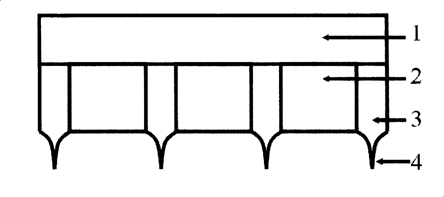
[0010] Such as figure 1 As shown, the present invention includes: a base portion 3 embedded in the gap between the microelectrodes 2 of the chip 1 and a protruding portion 4 higher than the microelectrodes 2 . The base part 3 completely fills the gap between the microelectrodes 2 , the length is the length of the microelectrodes 2 , the width is the distance between the microelectrodes 2 , and the height is the height of the microelectrodes 2 . The length of the protruding part 4 is also the length of the microelectrode 2 , the width is the distance between the microelectrodes 2 , and the height is about 4um-8um higher than the microelectrode 2 .

[0011] The shape of the protruding part 4 is a needle point shape, an inverted trapezoidal shape, a rectangle, and a triangle shape, wherein the preferred shape is a needle point shape, and the flanks of the needle point protruding part 4 are arc-shaped.

[0012] When using the preferred insulating glue structure of the present inv...


PUM


Abstract

The present invention relates to a microelectrode short circuit proof squilgee structure, belonging to microelectronic technique field. Said invention includes base embed in microelectrode interval and bulge above microelectrode, wherein base part completely filling microelectrode interval and having same length, width and height with that of microelectrode, said bulge having height higher 4-8 micrometer than that of microelectrode, the optimized shape being pinpoint shape its flank being arcs of circles shape. Said invented squilgee not only can effectively prevent short circuit due to adjacent microelectrode interspaceal conducting particles bridging, but also prevent short circuit due to conducting particles bridging between adjacent microelectrode pressure welding layers.

Description

technical field [0001] The present invention relates to a structure in the technical field of microelectronics, in particular to a micro-electrode short-circuit proof isolation glue structure. Background technique [0002] In the field of semiconductor packaging or liquid crystal display (LCD), the anisotropic conductive adhesive is directly used to mount the semiconductor chip on the substrate, such as connecting the chip to the LCD (or FPC). Through the hot pressing process, the chip is directly flipped on the substrate with anisotropic conductive adhesive. Between the micro-electrodes of the chip and the pads of the substrate corresponding thereto, a plurality of conductive particles deformed under pressure are sandwiched, and the electrical connection between the upper and lower micro-electrodes is realized by these deformed conductive particles. At the same time, the chip and the substrate are cured by the epoxy resin substrate of the anisotropic conductive adhesive to...

Claims


Application Information

Patent Timeline
Patent Type & Authority Patents(China)
IPC IPC(8): H01L23/482
Inventor 丁汉谢斌吴懿平
Owner SHANGHAI JIAOTONG UNIV
Learn More