

Refrigerator and control method thereof
A control method and refrigerator technology, which are applied to household refrigerators, freezers, refrigeration components, etc., can solve the problems of slow operation of refrigerants, inability to obtain cooling effects, inability to correctly control the circulation volume of refrigerants, etc. The effect of the increase in input power
- Summary
- Abstract
- Description
- Claims
- Application Information
AI Technical Summary
Problems solved by technology
Method used
Image

Examples
no. 1 Embodiment
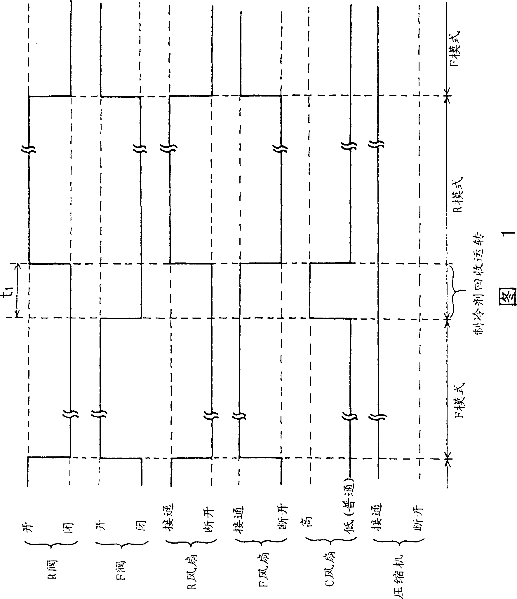
[0070] Hereinafter, a first embodiment of the present invention will be described with reference to FIGS. 1-3 .
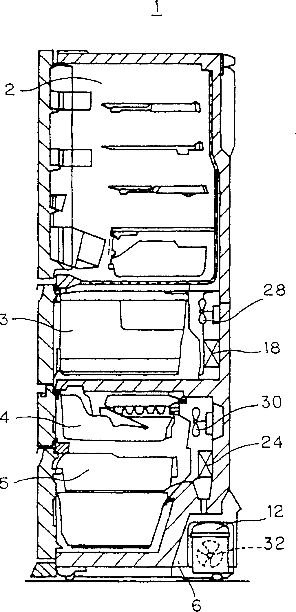
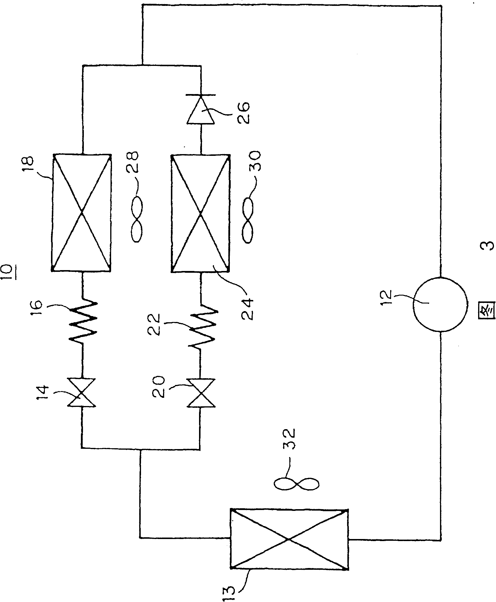
[0071] Fig. 1 is a timing control flowchart of the control state in the refrigerator 1 of the present embodiment. figure 2 It is a longitudinal sectional view of the refrigerator 1. FIG. 3 shows the refrigeration cycle 10 of the refrigerator 1 .
[0072] First, according to figure 2 , illustrating the structure of the refrigerator 1.
[0073] Refrigerator 1 is provided with refrigerating chamber 2, vegetable chamber 3, ice making chamber 4 and freezing chamber 5 respectively from the upper stage.
[0074] A compressor 12 is provided in the machine compartment 6 at the back of the freezer compartment 5 . In addition, an F evaporator 24 and an F fan 30 are provided on the back of the ice making compartment 4 . In addition, an R evaporator 18 and an R fan 28 are provided on the back side of the vegetable compartment 3 . Further, a condenser fan (hereinafter refe...
no. 2 Embodiment
[0089] Below, refer to Figure 4 , make an explanation with respect to the 2nd embodiment.
[0090] The present embodiment differs from the first embodiment in that the termination time of the refrigerant recovery operation from the F mode to the R mode is determined based on the outlet temperature of the F evaporator 24 .
[0091]The F evaporator 24 operates at a temperature of about -25°C in the F mode, but when transitioning from the F mode to the R mode, as described in the first embodiment, the F valve 20 is closed and the F fan 30 is driven. In this state, the C fan 32 is operated at a high speed.
[0092] In this way, the refrigerant remaining in the F evaporator 24 evaporates due to the temperature in the refrigerator. Also, the inside of the F evaporator 24 is in a vacuum state due to the pumping by the compressor 12 . Thus, the temperature of the F evaporator 24 is set as Figure 4 Shown gradually decreases.
[0093] However, since there is no heat exchange with...
no. 3 Embodiment
[0096] Hereinafter, referring to FIG. 5, a third embodiment will be described.
[0097] The difference is that in the first embodiment, when the refrigerant recovery operation is terminated, the operation is switched to the R mode, but in this embodiment, the R fan 28 is not directly rotated at this time, but even at the beginning its stopped.
[0098] That is, after switching from the refrigerant recovery operation to the R mode, the operation of the R fan 28 is stopped immediately. Then, the stopped state of the R fan 28 is continued until the outlet temperature of the R evaporator 18 decreases. Also, the R fan 28 may be stopped only for the set time t2.
[0099] The reason for the operation as described above is that if the refrigerating room 2 and the vegetable room 3 increase (temperature) in the F mode, in this state, the refrigerant flows and the R fan 28 is rotated, and then evaporates in the R evaporator 18. Refrigerant liquid, forming a vapor. As a result, the pr...
PUM
 Abstract
Description
Claims
Application Information