Method for preparing wave guide and grating structure of adjustable distributive feedback quantum cascade laser and above said grating

A technology of distributed feedback and quantum cascade, which is applied in the structure of optical waveguide semiconductors, the structure of optical resonators, lasers, etc., can solve the problem of rising laser threshold current density, increasing laser waveguide loss, laser mode and plasmon coupling Strong and other issues

Inactive Publication Date: 2008-07-23
SHANGHAI INST OF MICROSYSTEM & INFORMATION TECH CHINESE ACAD OF SCI
View PDF4 Cites 0 Cited by
  • Summary
  • Abstract
  • Description
  • Claims
  • Application Information

AI Technical Summary

Problems solved by technology

This will cause the metal electrode at the grating groove to be in contact with the low-doped semiconductor layer, and the refractive index of the high-loss metal-semiconductor interface plasmons formed is very close to the effective refractive index of the laser mode, so that the laser mode and the plasmonic The element coupling is strong, which greatly increases the waveguide loss of the laser, and finally leads to a sharp increase in the threshold current density of the laser

Method used


Image

  • Method for preparing wave guide and grating structure of adjustable distributive feedback quantum cascade laser and above said grating
  • Method for preparing wave guide and grating structure of adjustable distributive feedback quantum cascade laser and above said grating
  • Method for preparing wave guide and grating structure of adjustable distributive feedback quantum cascade laser and above said grating

Examples


Embodiment 18

[0041] Embodiment 18.4 μm InGaAs / AlInAs / InP distributed feedback quantum cascade laser

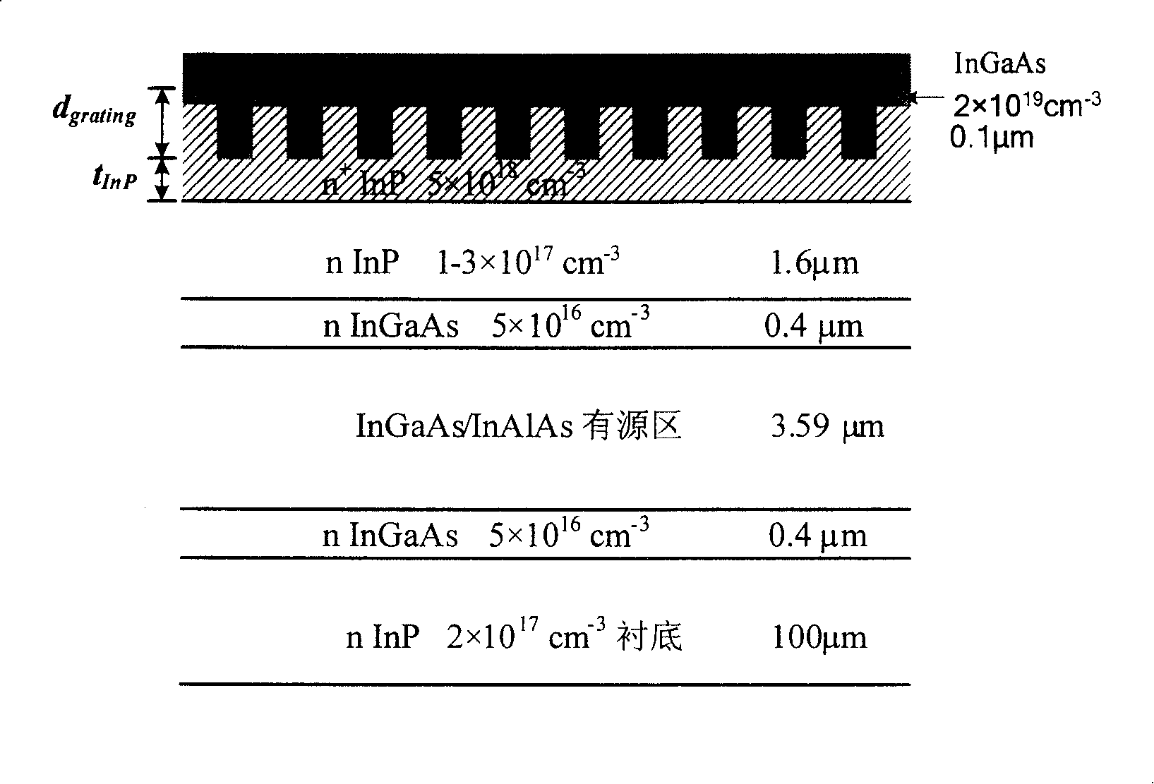
[0042] figure 1 A schematic diagram of the waveguide and grating structure of the InGaAs / AlInAs / InP tunable distributed feedback quantum cascade laser with a wavelength of 8.4 μm. The active layer region includes 60 periods of "active layer + injection region" structure with a thickness of 3.59 μm. The thickness of the upper and lower active regions is 0.4 μm, and the n-type doping concentration is 5×10 16 cm -3 InGaAs waveguide layer. Above the upper waveguide layer is an n-type moderately doped confinement layer InP (1-3×10 17 cm -3 , thickness 1.6μm), n-type heavily doped InP confinement layer (5×10 18 cm -3 , thickness 1.0μm), and n-type heavily doped InGaAs capping layer (2×10 19 cm -3 , thickness 0.1 μm). The substrate is moderately doped n-type InP (2×10 17 cm -3 ).

[0043] Using the method described in the summary of the invention in the specification of the invention...

Embodiment 27

[0048] Example 27.7 μm InGaAs / AlInAs / InP distributed feedback quantum cascade laser

[0049] Figure 6 It is the waveguide structure of InGaAs / InP tunable distributed feedback quantum cascade laser with laser wavelength of 7.7 μm. The active layer region includes 60 periods of "active layer + injection region" structure with a thickness of 2.66 μm. The thickness of the upper and lower active regions is 0.7μm, and the n-type doping concentration is 5×10 16 cm -3 InGaAs waveguide layer. Above the upper waveguide layer is an n-type moderately doped confinement layer InP (1-3×10 17 cm -3 , thickness 1.6μm), n-type heavily doped InP confinement layer (5×10 18 cm -3 , thickness 0.7μm), and n-type heavily doped InGaAs cap layer (2×10 19 cm -3 , thickness 0.1 μm). The substrate is moderately doped n-type InP (2×10 17 cm -3 ).

[0050] According to the same design principle and combined with numerical calculations, we designed the thickness of the heavily doped InGaAs cap ...


PUM


Abstract

This invention relates to a waveguide and a grating structure of an adjustable distribution feed back quanta cascade laser obtaining low threshold value current density and high side mode suppression ratio and a method for preparing first order grating of laser meeting the requirement, in which, the laser waveguide and the grating structure is a limit structure in the waveguide made up of a deep first order grating and a thin heavy doped semiconductor layer, said grating corrosion technology is to utilize the InGaAs / InP structure as the corrosion sacrificial layer of the grating and select different corroding liquid matches to get a grating structure with the depth adjustable and accuracy controllable.

Description

technical field [0001] The invention relates to a structure of a waveguide and a grating of a distributed feedback quantum cascade laser and a preparation method of the grating, belonging to the field of semiconductor optoelectronics. Background technique [0002] Distributed feedback quantum cascade lasers can provide tunable single-mode lasers in the mid- and far-infrared bands, and can be used as light sources for semiconductor absorption spectra to detect various trace gases with high sensitivity, such as CO 2 、CH 4 , HCl, NO 2 , N 2 O, etc., so it has important application prospects in air quality detection, medical diagnosis, industrial control and other fields. [0003] In order to facilitate the application and improve the sensitivity of gas detection, the distributed feedback quantum cascade laser is required to work in the continuous mode at room temperature. However, so far, only distributed feedback quantum cascade lasers (DFB QCL) with very few wavelengths h...

Claims


Application Information

Patent Timeline
Patent Type & Authority Patents(China)
IPC IPC(8): H01S5/12H01S5/20H01S5/343H01S5/00
Inventor 徐刚毅李耀耀李爱珍
Owner SHANGHAI INST OF MICROSYSTEM & INFORMATION TECH CHINESE ACAD OF SCI
Why Eureka
Try Eureka