Equipment management network monitoring system

A technology for network monitoring and equipment management, applied in general control systems, control/regulation systems, computer control, etc., can solve problems such as factory economic losses, difficulty in ensuring accuracy, and rough data, and improve the level of informatization and production. process, the effect of optimizing the manufacturing system

Inactive Publication Date: 2008-10-15
章近达
View PDF6 Cites 0 Cited by
  • Summary
  • Abstract
  • Description
  • Claims
  • Application Information

AI Technical Summary

Problems solved by technology

If you need some equipment operation data, such as equipment operation ratio, production process time, reports, etc., you can only rely on manual statistics afterwards to get rough data. If you want to get more detailed data, such as equipment operation Records, service response speed, etc., relying on the current traditional method of manual statistics, it is far from being able to achieve, that is, the equipment operation status indication and statistics of some equipment itself are only individual data, so it cannot be done at present. Real-time status monitoring and statistics to the whole factory
In view of the existence of the above-mentioned traditional equipment management mode, once a situation occurs on the equipment site, the operator must seek help everywhere, which not only wastes the time of the operator, but also wastes the precious running time of the equipment, and even brings serious economic losses to the factory. Therefore, the existing traditional management model is largely one-sided, passive and blind
[0003] In the traditional equipment management mode, the recording work needs to be manually recorded by the operator in written form. Usually, this kind of data is a rough description of the actual situation and the cause of the situation by the operator, and its accuracy is difficult to guarantee, so these data are very difficult. It is difficult to play a substantive role, and statisticians have to spend a lot of time and energy to input and edit daily, weekly and monthly record reports

Method used


Image

  • Equipment management network monitoring system

Examples


Embodiment Construction

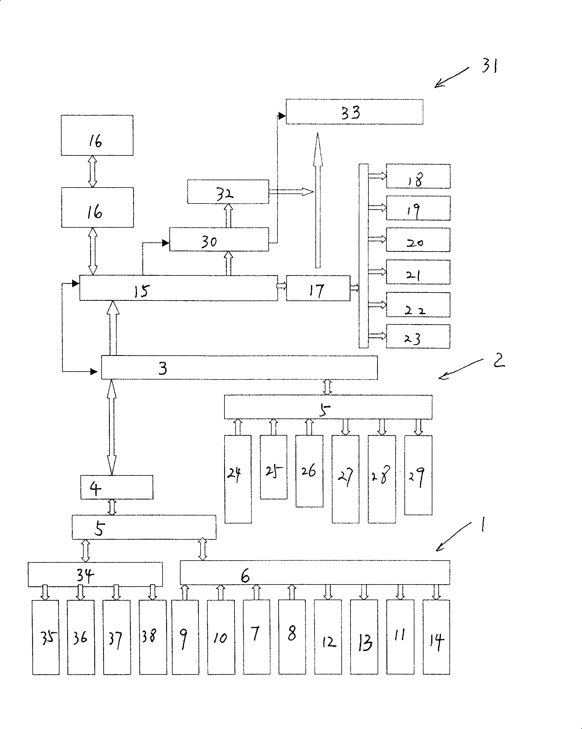
[0015] The standard configuration of the present invention takes 15 devices as a group, 16 constitutes 1 system unit, and a system unit can monitor up to 240 devices; multiple systems can share a database to monitor thousands or even tens of thousands of devices, the specific quantity It depends on the performance of the enterprise computer network and the capacity of the data server.

[0016] The present invention is mainly composed of a field device bus network system 1 and a computer device monitoring system 2. The field device bus network system 1 uses a high-performance programmable logic controller PLC or an industrial computer 3 to cooperate with an intelligent remote module, and connects remotely through an industrial bus 4. The I / O module 5 samples data and connects with the terminal adapter 6 on the device side to realize the detection and display of the device status.

[0017] The terminal adapter in the field device bus network system mainly inputs the start signal 7 a...


PUM


Abstract

The present invention relates to an equipment management network monitoring system. It mainly consists of field equipment bus network system and computer equipment monitoring system, in which the field equipment bus network system utilizes the high-performance programmable logic controller PLC or industrial control computer to match intelligent remote module, and utilizes industrial bus and makes it connect with remote I / O module to sample data, and connected with terminal adapter of equipment terminal to implement detection and display of equipment state. The described system main machine utilizes RJ45 interface to connect to local area network and utilizes state indication interface to implement waiting state, so that said invention can have several characteristics of optimizing production system of factory, raising utilization rate of equipment and raising management level of equipment, etc.

Description

Technical field [0001] The invention relates to an equipment management system based on a field equipment bus network system and a computer system that is networked, informatized, capable of real-time and global monitoring of the operating status of all equipment in the field and automatically records real-time status data information, and belongs to equipment Management system. Background technique [0002] Under the existing equipment management mode, it is necessary to grasp the operating status of the equipment in the factory, whether it is equipment operators, equipment managers, or even high-level leaders, it can only be done through human observation and manual recording. , And the scope of observation is very small, you can only focus on the status of one or a few devices at a time. If you need some equipment operating data, such as equipment operating ratio, production process time, reports, etc., you can only rely on post-event manual statistics to get rough data. If yo...

Claims


Application Information

Patent Timeline
Patent Type & Authority Patents(China)
IPC IPC(8): G05B19/05G05B19/418G05B15/02G06F19/00
CPCY02P90/02
Inventor 章近达
Owner 章近达
Why Eureka
Try Eureka