Multi-tube pass type heat exchanger

A heat exchanger and multi-tube technology, applied in heat exchange equipment, heat exchanger types, indirect heat exchangers, etc., can solve problems such as low heat exchange efficiency, high manufacturing cost, and complex heat exchanger structure, and achieve Enhance heat transfer, save manufacturing costs, and improve the effect of emission performance indicators

Active Publication Date: 2009-02-11
BEIJING U BRIDGE CHAOYANG +1
View PDF12 Cites 0 Cited by
  • Summary
  • Abstract
  • Description
  • Claims
  • Application Information

AI Technical Summary

Problems solved by technology

[0005] The first type is the plate-fin heat exchanger, which is composed of many thin plates and the secondary surface between the plates. The secondary surface not only acts as a ribbed surface, but also plays the role of tube-sheet spacing and enhances rigidity. This type of heat exchanger The structure of the switch is complex and the manufacturing cost is high
[0006] The second type is the shell-and-tube heat exchanger, and the shell-and-tube heat exchanger is provided with many parallel tubes in a cylindrical shell (these parallel tubes are called tube bundles), and the hot and cold fluids are separated from the space in the tubes. (tube side) and the space outside the tube (shell side) flow through for heat exchange; usually a longitudinal partition parallel to the tube bundle or a baffle perpendicular to the tube bundle is installed on the shell side; to increase the flow velocity of the fluid and enhance the disturbance, Improve heat transfer efficiency; this type of heat exchanger has a simple structure, but the heat transfer efficiency is low

Method used


Image

  • Multi-tube pass type heat exchanger
  • Multi-tube pass type heat exchanger
  • Multi-tube pass type heat exchanger

Examples


Embodiment 1

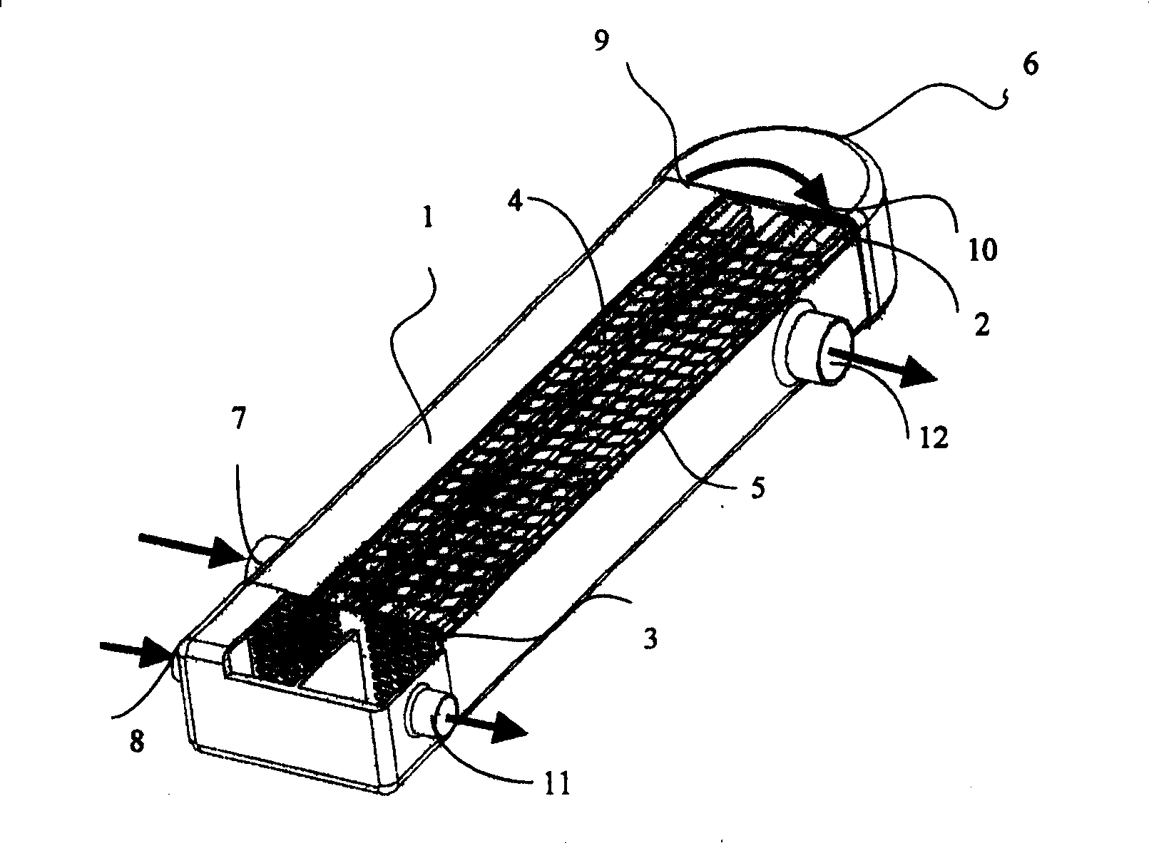
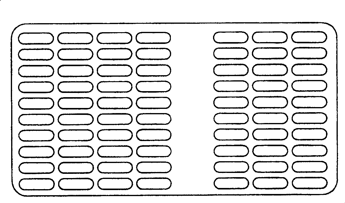
[0037] see figure 1 and figure 2 , is an embodiment in which the heat exchange tubes are divided into two tubes, wherein a fixed tube plate 3 is provided at both ends of the shell 1, and a fixed through hole for the heat exchange tube 2 is opened on the tube plate 3, and the heat exchange tube The nozzle ends of 2 are respectively welded in the corresponding holes on the tube sheet 3, and fixed in the shell 1 parallel to each other.

[0038] The heat exchange tubes 2 form the first tube pass 4 and the second tube pass 5, the exhaust gas outlet port of the engine is connected with the exhaust gas inlet port 8 of the first tube pass 4, the exhaust gas outlet port 9 of the first tube pass 4 is connected with the second tube pass The exhaust gas inlet port 10 of 5 is interconnected through the head 6 fixed on the casing 1, and the exhaust gas outlet port 11 of the second tube pass 5 is connected with the engine air inlet. The sealing head 6 has an arc-shaped curved surface to f...

Embodiment 2

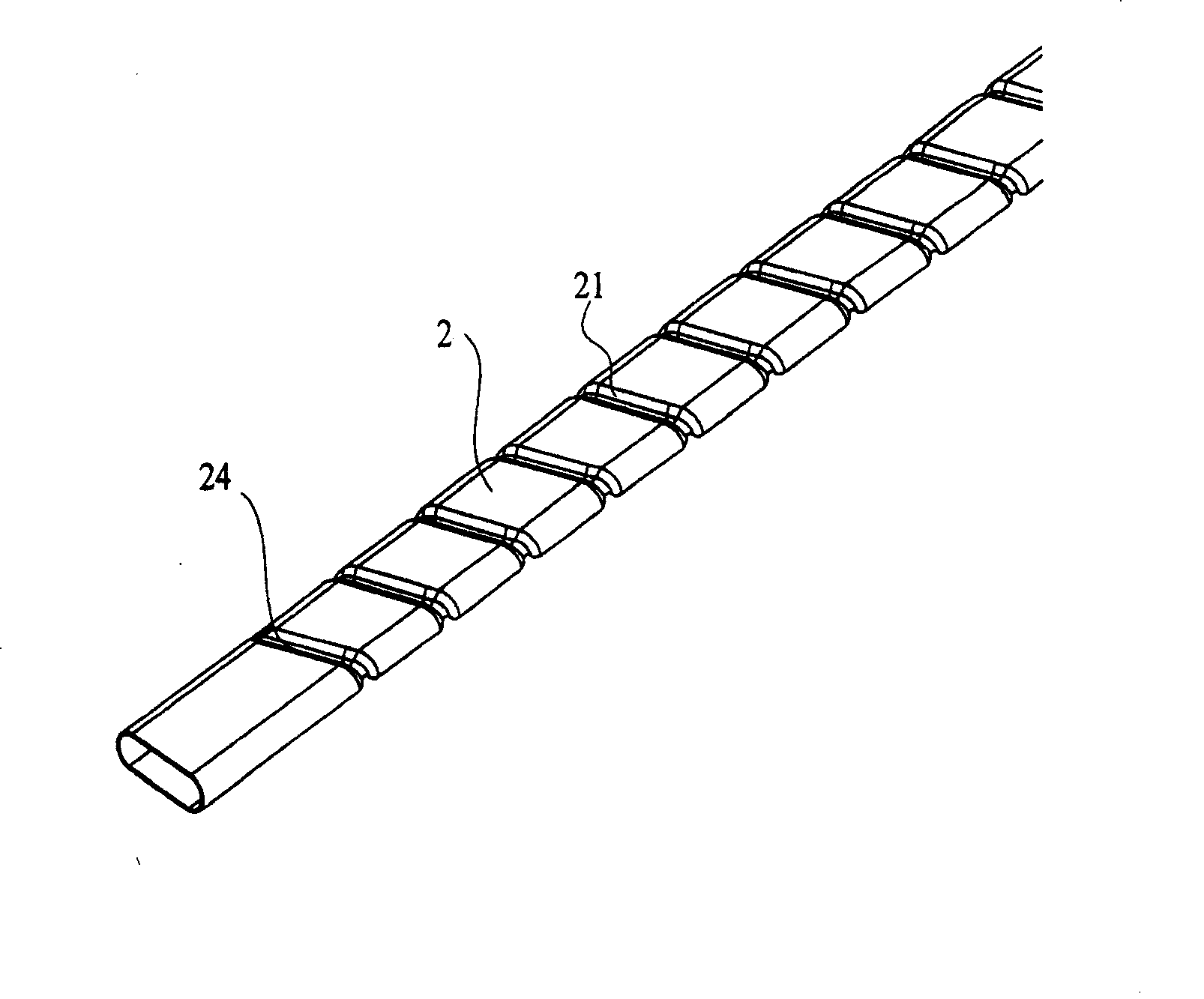
[0048] see figure 1 and Figure 4 , the fixed heat exchange tube 2 in the shell 1 is Figure 4 For the heat exchange tube with the first cross-sectional shape shown, the cross-section of the heat exchange tube 2 is flat, the two relatively long sides 23 are straight lines, and the two opposite short sides 22 are arc-shaped convex from the inside to the outside, and are in line with the The long side 23 is an arc-shaped transition connection, which makes full use of the surface of the heat exchange tube to achieve heat exchange with maximum efficiency, and is easy to produce and process.

Embodiment 3

[0050] see figure 1 and Figure 5 , the fixed heat exchange tube 2 in the shell 1 is Figure 5 For the heat exchange tube with the second cross-sectional shape shown, the cross-sectional shape of the heat exchange tube 2 is approximately rectangular, and a circular arc-shaped transition connection is set between the adjacent two sides; such a setting is convenient for production and processing, and can also improve the heat exchange tube. heat transfer efficiency.


PUM


Abstract

The invention relates to a heat exchanger with multiple tube side, especially applied in exhaust gas recirculation cooling device in automobile engine system. The invention comprises shell and heat exchanging pipe. Pipe plates are set at two ends of said shell. Pipe ports of said heat exchanging pipe are welt on the pipe plate and are fixed in the shell in parallel. Double tube side is constituted by said heat exchanging pipe groups and is divided into a first tube side and a second tube side. The quality of heat exchanging pipes in the first tube side is more than the one in the second tube side. The height of sections of said heat exchanging pipe is different from the width and it is flat shape. Grooves are set on said heat exchanging pipe on the outer surface. Said grooves are convex on the inner surface of heat exchanging pipe and the shape is corresponding to the groove. The invention can improve heat exchanging efficiency by 25-40%, decrease emission of NOx in automobile engine, and shorten length and cubage of heat exchanger. The invention is provided with simple and compact structure, low scaling and low manufacture and maintenance cost.

Description

technical field [0001] The invention relates to a heat exchanger, in particular to a multi-tube heat exchanger, which is suitable for use in exhaust gas recirculation systems of automobile engines, and is used as a cooler for reducing emissions of nitrogen oxides (NOx) , is also suitable for use as an intercooler in a turbocharger system to improve engine performance. Background technique [0002] Heat exchangers are used in various industrial sectors such as power, metallurgy, chemical industry, oil refining, construction, machinery manufacturing, food, medicine and aerospace. Therefore, the optimal design of heat exchangers is particularly important for various industries. With increasingly stringent emission standards around the world, heat exchangers in automotive exhaust gas recirculation cooling systems are critical. [0003] Exhaust gas recirculation cooling technology is in the well-known automobile engine exhaust gas recirculation system. Part of the exhaust gas e...

Claims


Application Information

Patent Timeline
Patent Type & Authority Patents(China)
IPC IPC(8): F28D7/10F28F1/06F28F1/12
Inventor 景建周景建坤杨晓瑷沈董浩汤俊洁
Owner BEIJING U BRIDGE CHAOYANG
Why Eureka
Try Eureka