
Parallel-working sine ware inverter

A sine wave and inverter technology, which is applied in the field of sine wave inverter parallel control, can solve the problems of reducing system reliability and increasing system hardware complexity, and achieves the effect of high reliability and strong communication immunity

Inactive Publication Date: 2009-02-11
NANJING UNIV OF AERONAUTICS & ASTRONAUTICS
View PDF6 Cites 1 Cited by
  • Summary
  • Abstract
  • Description
  • Claims
  • Application Information

AI Technical Summary

Problems solved by technology

[0005] The main disadvantage of this parallel scheme is that the same frequency and same phase control of the square wave synchronous signal of each parallel module must be completed through two signal interconnection lines between each module, and the existence of signal interconnection lines still increases the hardware complexity of the system performance, reducing the reliability of the system

Method used


Image

  • Parallel-working sine ware inverter
  • Parallel-working sine ware inverter
  • Parallel-working sine ware inverter

Examples


Embodiment Construction

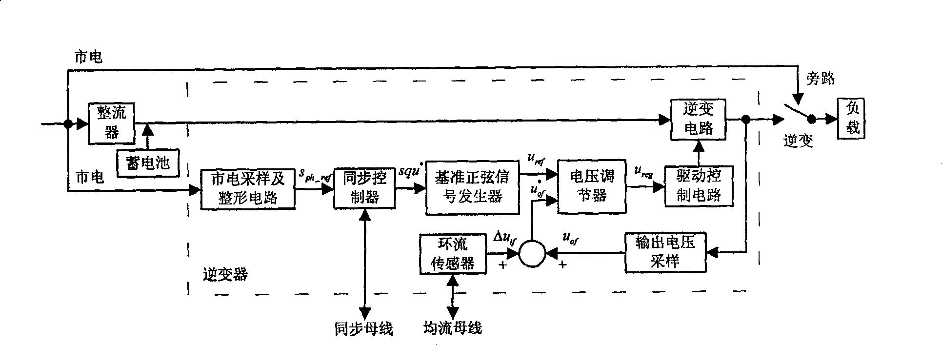
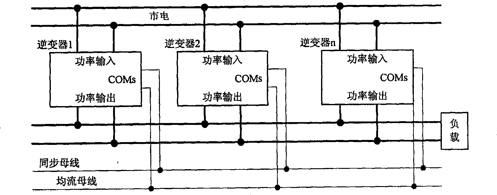
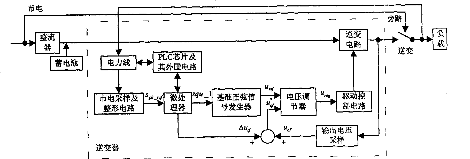
[0019] The principle block diagram of the sine wave inverter and the online uninterruptible power supply UPS of the present invention are as follows image 3 As shown, its structure is the same as figure 1 The difference lies in: First, the input signal of the reference sine signal generator, that is, the generation method of the square wave synchronous signal has changed, image 3 canceled in figure 1 In the synchronous bus, the PLC chip and its peripheral circuits, power lines and other links are added. The PLC communication power line is connected to the total output end of the UPS, and the microprocessor obtains s according to the power line voltage sampling and shaping circuit. ph_ref Information, the frequency and phase of the square wave synchronous signal of this module and other information are sent and received through the PLC circuit. Its function is to eliminate the reference voltage signal u of each inverter module in the parallel system. ref The circulation cau...


PUM


Abstract

The invention is a sine wave inverter able to operate in parallel, belonging to the sine wave inverter, comprising inverting circuit and inversion control circuit, where the inversion control circuit comprises PLC chip and the peripheral control circuit, power line, microprocessor, voltage sampling and shaping circuit, reference sine signal generator, voltage regulator, output voltage sampling circuit, adder and drive control circuit, applied to the parallel operating control of the sine wave inverter; when the power inverter parallel system is in various operating states, each square wave synchronous signal generated by one module is same-frequency and in-phase with the square wave synchronous signals generated by the other modules. And the invention needs no singal interconnections and has strong communication interference resistance and high reliability, applies to sine wave inverter control system without signal interconnections and implements completely electric isolation and hot socketing for various inverter modules and improves dynamic and static current equalizing characteristics of parallel systems.

Description

1. Technical field [0001] The invention belongs to the technical field of parallel control of sine wave inverters, and in particular relates to a method and realization technology for parallel operation of single-phase and three-phase sine-wave inverters, single-phase and three-phase on-line uninterruptible power supplies (UPS), and the like. 2. Background technology [0002] The control block diagram of an existing sine wave inverter that can work in parallel is as follows: figure 1 As shown, it includes two parts: the power unit and the inverter control unit composed of the inverter circuit. The inverter control unit mainly includes the mains sampling and shaping circuit, the output voltage sampling circuit, the reference sinusoidal signal generator, the voltage regulator and the drive control unit. circuit; it is characterized in that it also includes a synchronous controller connected between the mains sampling and shaping circuit and the reference sinusoidal signal gene...

Claims


Application Information

Patent Timeline
Patent Type & Authority Patents(China)
IPC IPC(8): H02M7/48H02J9/06H02J3/38H02J7/34
Inventor 何中一王笑娜邢岩
Owner NANJING UNIV OF AERONAUTICS & ASTRONAUTICS
Learn More