Electric assisting bicycles

A technology of bicycles and electric power, applied in the field of electric power-assisted bicycles

Inactive Publication Date: 2009-04-08
NTN CORP +1
View PDF9 Cites 2 Cited by
  • Summary
  • Abstract
  • Description
  • Claims
  • Application Information

AI Technical Summary

Problems solved by technology

In order to solve the defects of the existing direct coupling method, the relevant manufacturers have tried their best to find a solution, but no suitable design has been developed for a long time. This is obviously a problem that the relevant industry is eager to solve

Method used


Image

  • Electric assisting bicycles
  • Electric assisting bicycles
  • Electric assisting bicycles

Examples


Embodiment 1

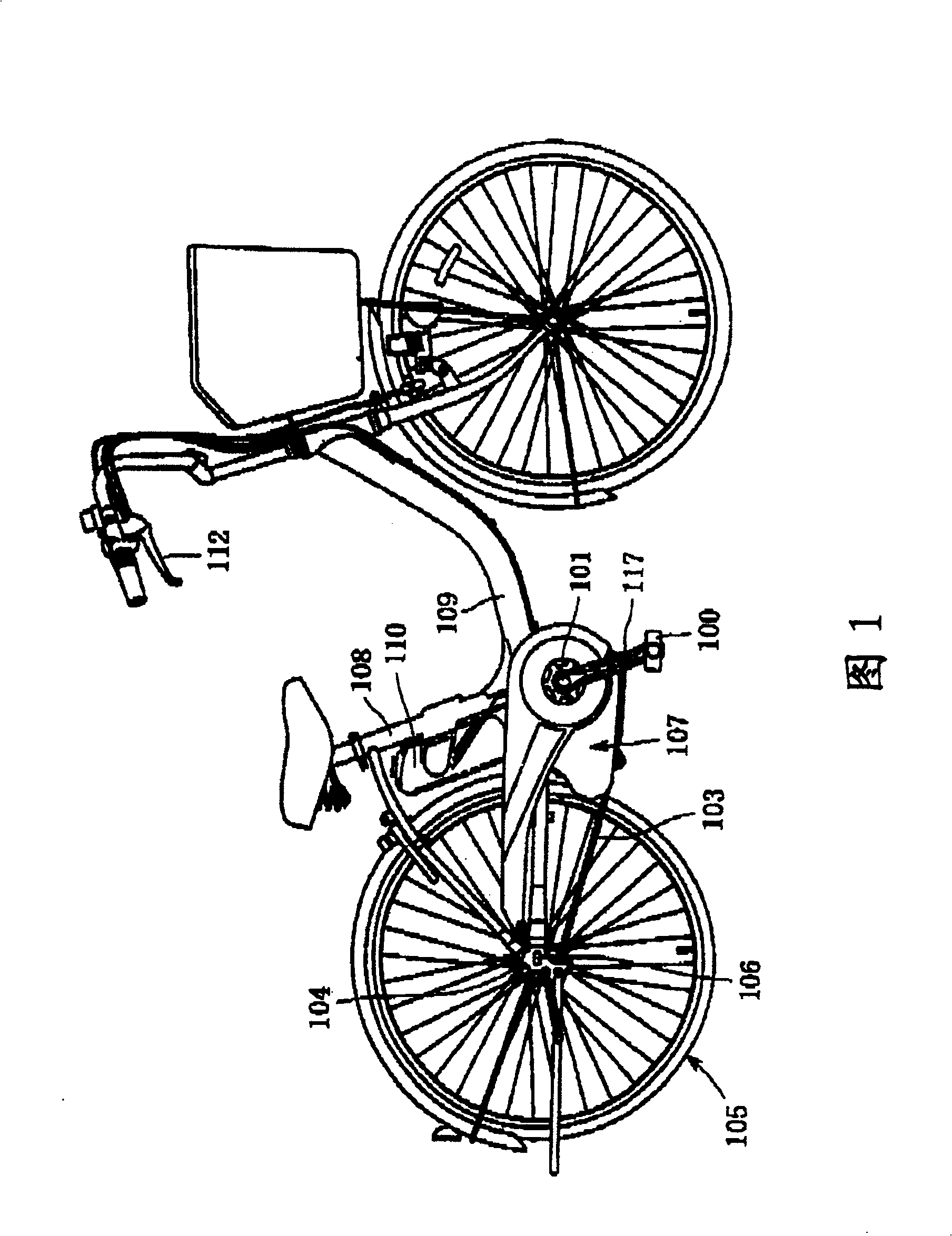
[0081] exist Figure 6a and 6b In the illustrated embodiment 1, the pedal driving force of the human drive system and the motor output of the motor drive system are combined on the drive shaft 106 which is closer to the output than the transmission tool 115 .

[0082] According to Embodiment 1, in the human power drive system, the pedal driving force acting on the pedal 100 is converted into the rotational motion of the crank shaft 101 in the crank 117, and the torque thereof is transmitted to the rear wheel 105 through the first transmission means 115a on the drive shaft 106. The first transmission 115a includes a front sprocket 102 attached to the crank shaft 101, a rear sprocket 104a attached to the rear wheel 105 drive shaft 106, and a chain 103a connected between the sprockets 102 and 104a. . The rear sprocket 104a is freely coupled to the drive shaft 106 via a well-known one-way clutch 119 (possibly using a ratchet coupling instead of wedge-like engagement, or other si...

Embodiment 1

[0091] The advantage of the structure of Embodiment 1 is that the internal structure of the motor device 107 is simple, and it can realize multi-stage transmission installed on the drive shaft 106 or a similar position.

Embodiment 2

[0093] exist Figure 7a and 7b In the illustrated embodiment 2, the pedal driving force in the human drive system and the motor output in the motor drive system are combined in the motor assembly 107 which is located near an input transmission means 115 . In other words, the combined driving force is output by the common sprocket 102 instead of disposing the sprockets 102 and 118 at the ends of the manual drive system and the motor drive system respectively as shown in the first embodiment above and the third embodiment below.

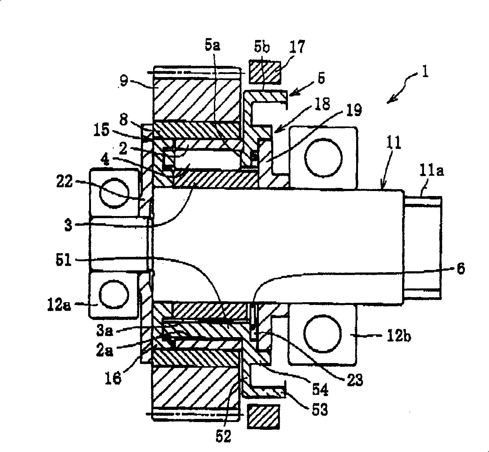
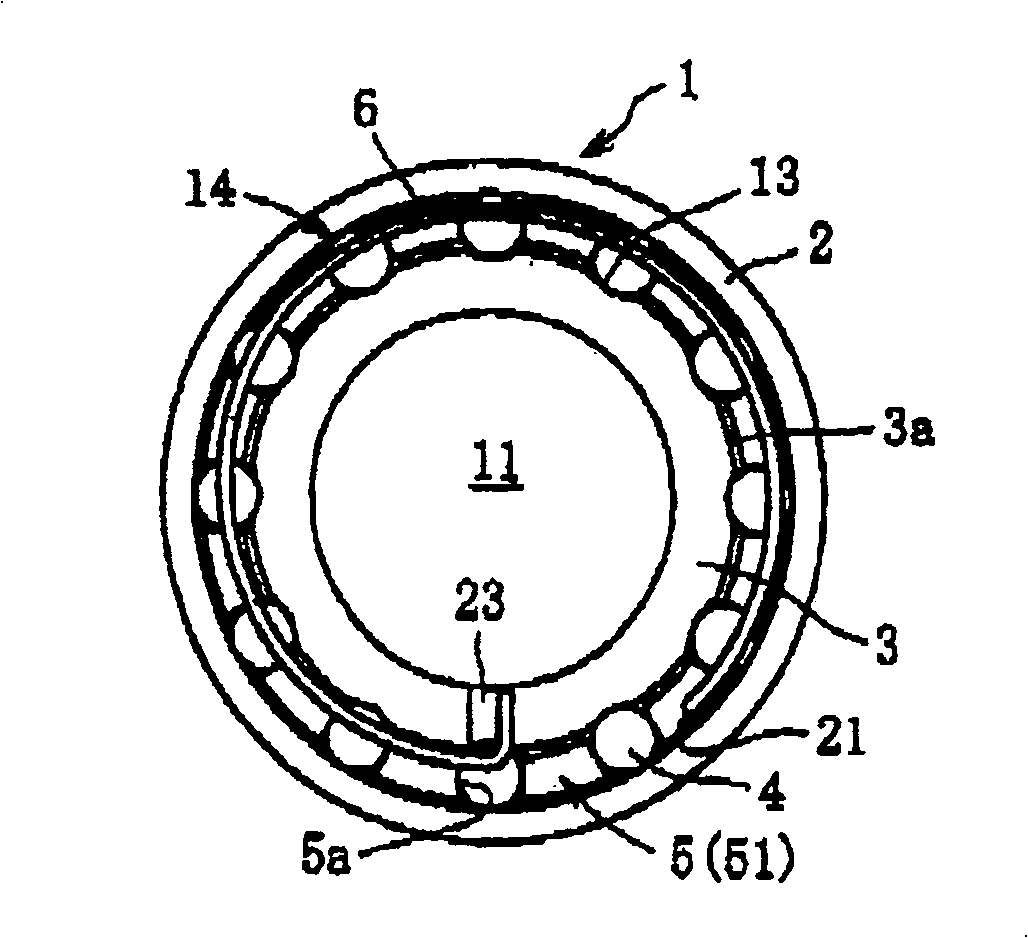
[0094] Specifically, in the manual drive system, the pedal driving force acting on the pedal 100 is transmitted to the clutch device through a path including a large gear 121, a one-way clutch 119, a transmission rod 122, a transmission gear 123 and an output gear 124. 1 on the output shaft 11 and combined with the motor output of the motor drive system transmitted to the output shaft 11 by the input gear 9 of the clutch device 1 . This combined driv...


PUM


Abstract

An electric assisted bicycle of simple structure is provided which is superior in the stability, reliability, and certainty of operation, and is provided with an electric power regenerative function and a brake assist function. A pedal force transmitted from a crank shaft (101) is transmitted to an axle shaft (106) via first transmission means (115a), and the output of a motor (114) as an assistant motive power is transmitted to the axle shaft (106) via a clutch unit (1), which can switch a lock direction in conjunction with brake operation by a cyclist, and second transmission means (115b).

Description

technical field [0001] The invention relates to an electric power-assisted bicycle which uses motor output as auxiliary power. Background technique [0002] An electric power-assisted bicycle includes a battery as a motor power supply, and the bicycle uses the output of the motor as auxiliary power when running on flat roads and uphill roads. However, there is always a range limit for the unit of electricity, so increasing the mileage becomes an urgent need. [0003] In response to this need, Japanese Patent Laid-Open Publication No.2001-213383 (referred to as the prior art in the following sections of this paper) discloses an invention in which the rotation of the wheel during braking can be used for regenerative power generation, and the battery is powered by the regenerative current Charge. In the prior art, the rotation of the motor-driven part is transmitted to the rear wheel through a one-way clutch device such as a ratchet structure, while the direct coupling method...

Claims


Application Information

Patent Timeline
Patent Type & Authority Patents(China)
IPC IPC(8): B62M23/02F16D15/00B62M1/10B62M6/40B62M6/45B62M6/60F16D41/08F16D41/28
CPCB60L7/12B60L2240/423B60L2200/12B60L7/26B60L11/007B62M6/60B60L2250/24B60L11/1861B60L15/2009B60L11/1877Y02T10/72B60L50/20B60L50/66Y02T10/64Y02T10/70
Inventor 栗田昌弘福冈裕二带田直树
Owner NTN CORP
Why Eureka
Try Eureka