High power twister

A technology of yarn guiding device and package, which is applied in the direction of textiles and papermaking, etc. It can solve the problems of increased energy consumption, high yarn tension, and large moment of inertia, etc., and achieves easy manufacturing and installation, low yarn tension, and wide application range. Effect

Inactive Publication Date: 2009-04-15
WUHAN TEXTILE UNIV
View PDF6 Cites 2 Cited by
  • Summary
  • Abstract
  • Description
  • Claims
  • Application Information

AI Technical Summary

Problems solved by technology

Its main defects are: to process yarns of different raw materials, two-for-one twisting spindles with different structural sizes must be used. Spindle, that is, a two-for-one twisting spindle with a structure can only process a certain kind of raw material yarn, which obviously limits the application of two-for-one twisting spindles to a certain extent, and increases manufacturing and production costs; in order to achieve high productivity, two-for-one twisting The twisting spindle must adopt a high working speed (generally 10000-15000rpm), which will increase energy consumption, aggravate machine vibration and noise, and increase the design and manufacturing requirements and manufacturing cost of the spindle; when the two-for-one twisting spindle is working, the yarn produces an atmosphere, and the yarn High thread tension, easy to break, affect product quality, and require a special yarn tension regulator; produce fly, pollute the working environment
Its defects mainly include: when the spindle is twisting, the yarn package and the spindle cover in the spindle have to rotate at high speed with the spindle, the moment of inertia is large, and because the yarn package is difficult to achieve precise dynamic balance, the working speed of the spindle is still very high. High, it will inevitably produce greater vibration and noise; twisting efficiency needs to continue to improve
[0004] In recent years, people have paid attention to the development of high-power twisting machinery. Zhejiang Rifa Company has also proposed the idea of ​​a four-fold twisting spindle. However, its structure is too complicated to manufacture and use in actual production.

Method used


Image

  • High power twister
  • High power twister
  • High power twister

Examples


Embodiment 1

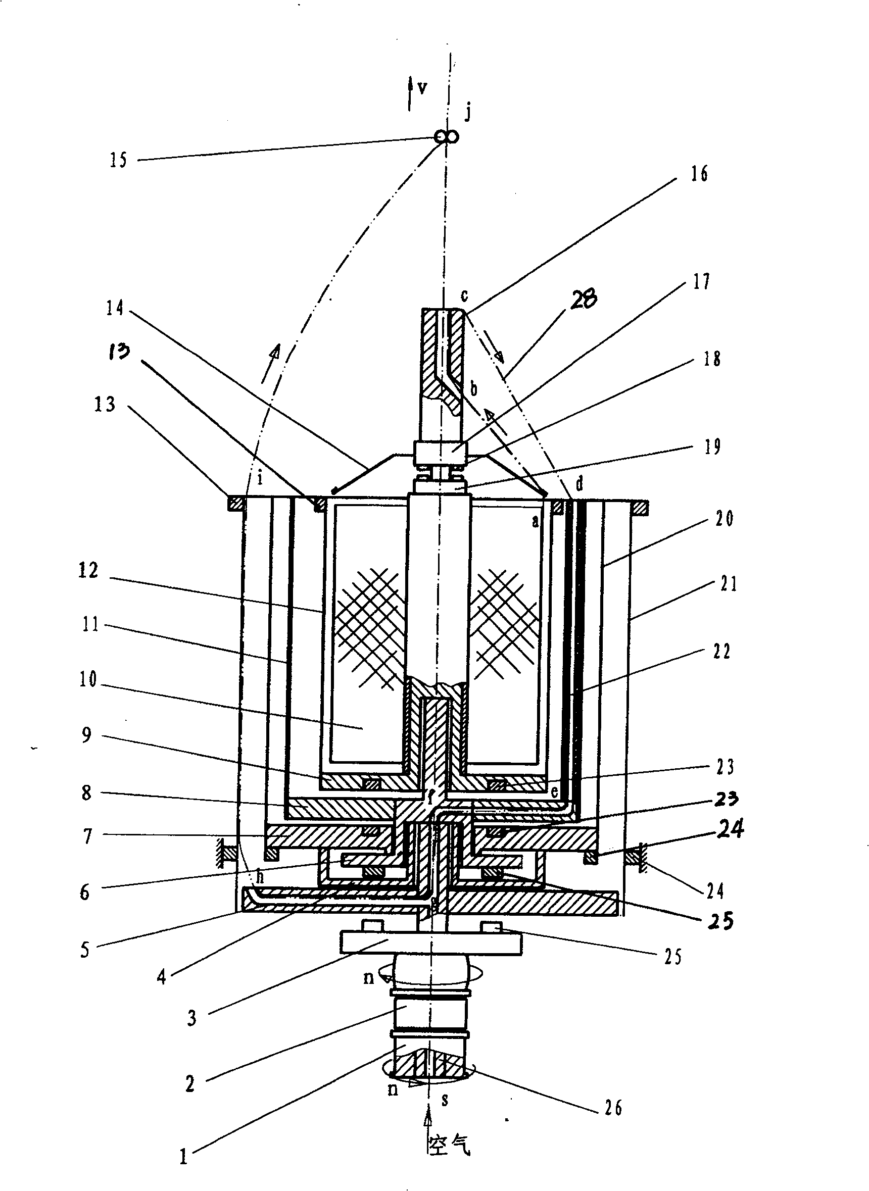
[0041] Such as figure 1 As shown, the high-power twisting device consists of a lower pulley 1, a support beam 2, an inner spindle drive plate 3, a static support sleeve 4, an outer spindle plate 5, an upper rotary magnet seat spindle rod 6, a static support seat 7, and an upper rotary Spindle disk 8, package support member 9, package 10, middle spindle cylinder 11, inner spindle cylinder 12, upper fixed magnet 13, yarn withdrawal frame 14, yarn guide hook 15, spindle end yarn guide rod and yarn guide nozzle 16, Upper tension ring 17, tension adjustment magnet 18, lower tension ring 19, middle spindle cylinder 20, outer spindle cylinder 21, yarn feeding guide 22, package fixed magnet 23, lower fixed magnet 24, driving magnet 25, and lower spindle rod 26 . It is divided into an outer spindle device, an intermediate spindle device, an inner spindle device, a supporting package mechanism, a yarn withdrawal guide device, and an outer spindle cylinder mechanism.

[0042] The outer...

Embodiment 2

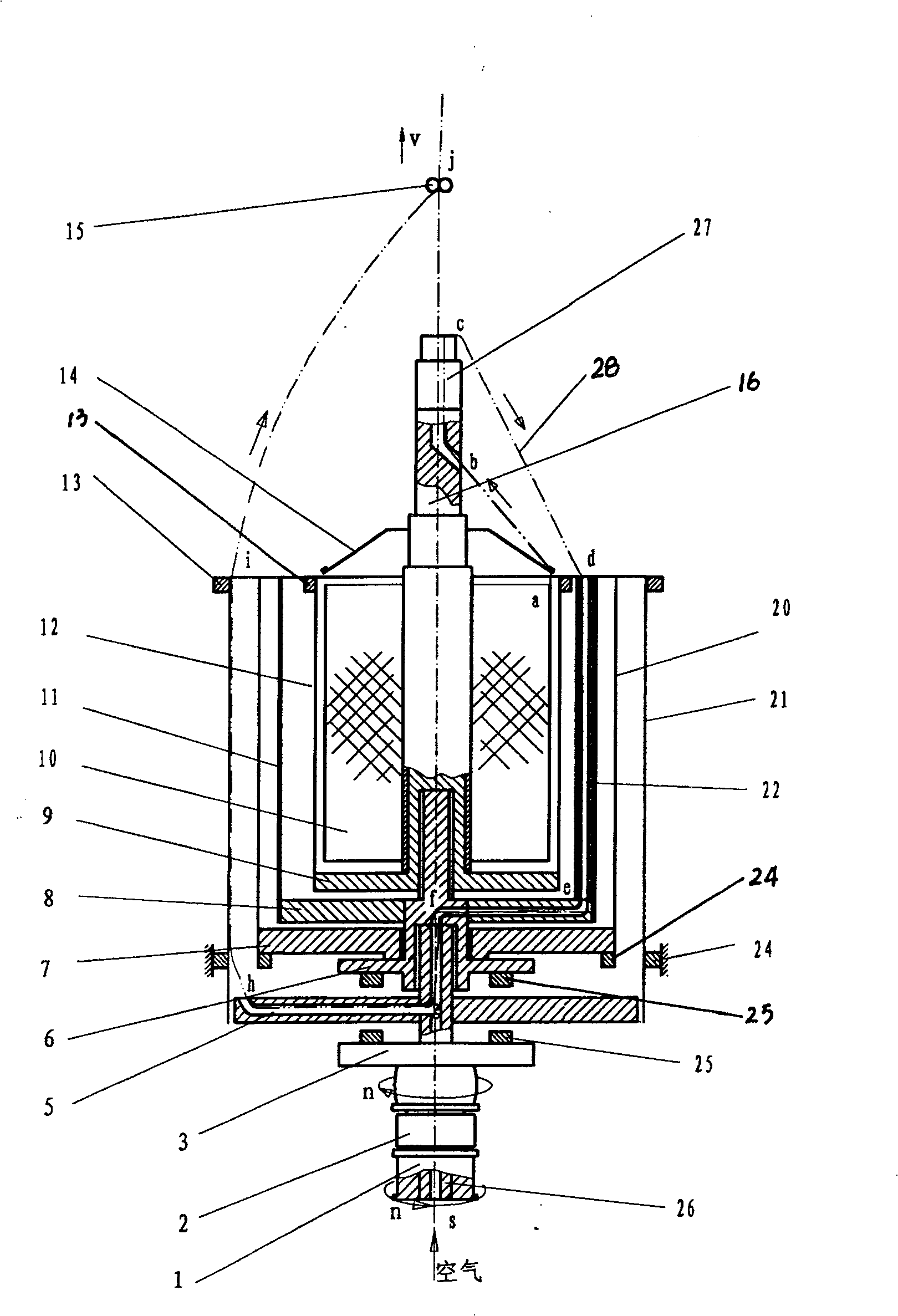
[0051] Such as figure 2 As shown, the high-power twisting device consists of a lower pulley 1, a support beam 2, an inner spindle drive disk 3, an outer spindle disk 5, an upper rotary magnet seat spindle rod 6, a static support seat 7, an upper rotary spindle disk 8, a coil Mounting support 9, package 10, intermediate spindle cylinder 11, inner spindle cylinder 12, upper fixed magnet 13, yarn withdrawal frame 14, yarn guide hook 15, spindle end yarn guide rod and yarn guide nozzle 16, intermediate spindle cylinder 20, The outer spindle cylinder 21, the yarn feeding guide 22, the lower fixed magnet 24, the drive magnet 25, the lower spindle rod 26, and the spring tensioner 27 are composed.

[0052] This embodiment is basically the same as Embodiment 1, except that: 1. This embodiment has no static support sleeve 4, and the upper rotary magnet seat spindle rod 6 is directly connected with the upper end of the lower spindle rod 26 by a bearing; 2. This embodiment For example, ...

Embodiment 3

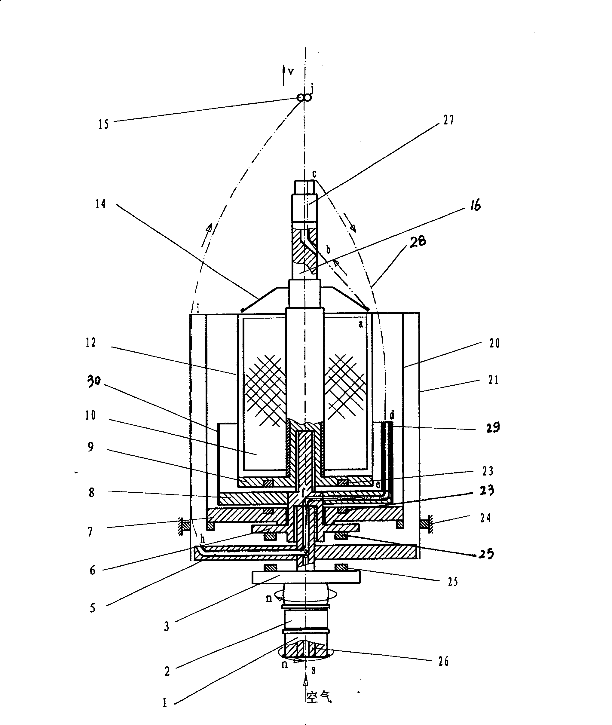
[0055] High-power twisting device, which consists of lower pulley 1, support beam 2, inner spindle drive disk 3, outer spindle disk 5, upper rotary magnet seat spindle rod 6, static support seat 7, upper rotary spindle disk 8, and coil support 9. Package 10, inner spindle cylinder 12, yarn return frame 14, yarn guide hook 15, spindle end yarn guide rod and yarn guide nozzle 16, intermediate spindle cylinder 20, outer spindle cylinder 21, yarn feeding guide tube 22, package fixation Composed of magnet 23, lower fixed magnet 24, driving magnet 25, lower spindle bar 26, spring tensioner 27, short yarn feed guide 29, and short intermediate cylinder 30,

[0056]This embodiment is basically the same as Embodiment 1, except that: 1. This embodiment has no static support sleeve 4, and the upper rotary magnet seat spindle rod 6 is directly connected with the upper end of the lower spindle rod 26 by a bearing; 2. Embodiment 1. The high intermediate spindle tube 11 and the yarn feed guid...


PUM


Abstract

The invention relates to a twisting device in the textile fiber twisting field. It is a high power twisting device, its character: it is composed of outer ingot device, inner ingot device, middle ingot device, package support mechanism, yarn retreating and guiding device and outer ingot cylinder mechanism, where the ingot rod of top rotary magnet base of the inner ingot device is supported on the top of the bottom ingot rod of the outer ingot device through the bearing, the static support base of the middle ingot device is supported on the ingot rod of top rotary magnet base through the bearing, the package support component of the package support mechanism on the top end of the ingot rod of top rotary magnet base through the bearing, the ingot-end cord rod and mouth are actively covered on the top end of the package support component, the outer ingot cylinder mechanism is outside the inner ingot device and the outer ingot cylinder is fixed with the frame. It has characters of rotation-rotation yarn feeding and 4 twisting rounds, simple structure, etc.

Description

technical field [0001] The invention relates to a twisting device in the field of textile fiber twisting, in particular to a high-magnification twisting spindle. Background technique [0002] The known two-for-one twist spindle, that is, the spindle turns once and adds two twists to the yarn, has been widely used in the spinning industry at present. Its main defects are: to process yarns of different raw materials, two-for-one twisting spindles with different structural sizes must be used. Spindle, that is, a structure type of two-for-one twisting spindle can only process yarns of a certain kind of raw material, which obviously limits the application of two-for-one twisting spindles to a certain extent, and increases manufacturing and production costs; in order to achieve high productivity, two-for-one twisting The twisting spindle must adopt a high working speed (generally 10000-15000rpm), which will increase energy consumption, aggravate machine vibration and noise, incre...

Claims


Application Information

Patent Timeline
Patent Type & Authority Patents(China)
IPC IPC(8): D01H7/86
Inventor 梅顺齐
Owner WUHAN TEXTILE UNIV
Why Eureka
Try Eureka