Supercharge Your Innovation With Domain-Expert AI Agents!

Speed differential mechanism of winching grinder

A technology of differential mechanism and winch mill, applied in the direction of spring mechanism, hoisting device, etc., can solve the problem of aggravated deformation, fracture, machining accuracy, assembly process constraints, gear pin shaft 211 can not well reflect synergy, etc. problem to ensure safety

Inactive Publication Date: 2009-04-29
常熟市常福电力机具有限公司
View PDF7 Cites 1 Cited by
  • Summary
  • Abstract
  • Description
  • Claims
  • Application Information

AI Technical Summary

Problems solved by technology

It can be seen from this that one group of gear pin shafts 211 is in a cantilever state, that is to say that the tops (right end in the figure) of one group of gear pin shafts 211 do not have any parts to give coupling tubes, and are very prone to deformation during use, and even due to Fracture caused by fatigue leading to major accidents
Moreover, the applicant has carried out actual test observation and analysis on a group of gear pin shafts 211 of the above-mentioned structure, and the result is that a group of gear pin shafts 211 cannot well reflect the joint action, that is, they cannot bear forces at the same time, and often appear as one group of gear pin shafts 211. Every two cams are under force when they are perpendicular to the left and right cams 11 and 12, and the rest are in a negative state, which also increases the probability of deformation and fracture
In theory, it seems that the above situation will not occur, but due to the objective constraints of machining accuracy and assembly technology, the above phenomenon is inevitable.

Method used


Image

  • Speed differential mechanism of winching grinder
  • Speed differential mechanism of winching grinder
  • Speed differential mechanism of winching grinder

Examples


Embodiment Construction

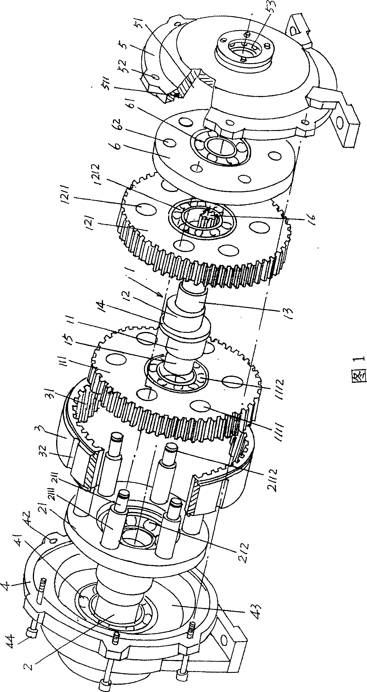
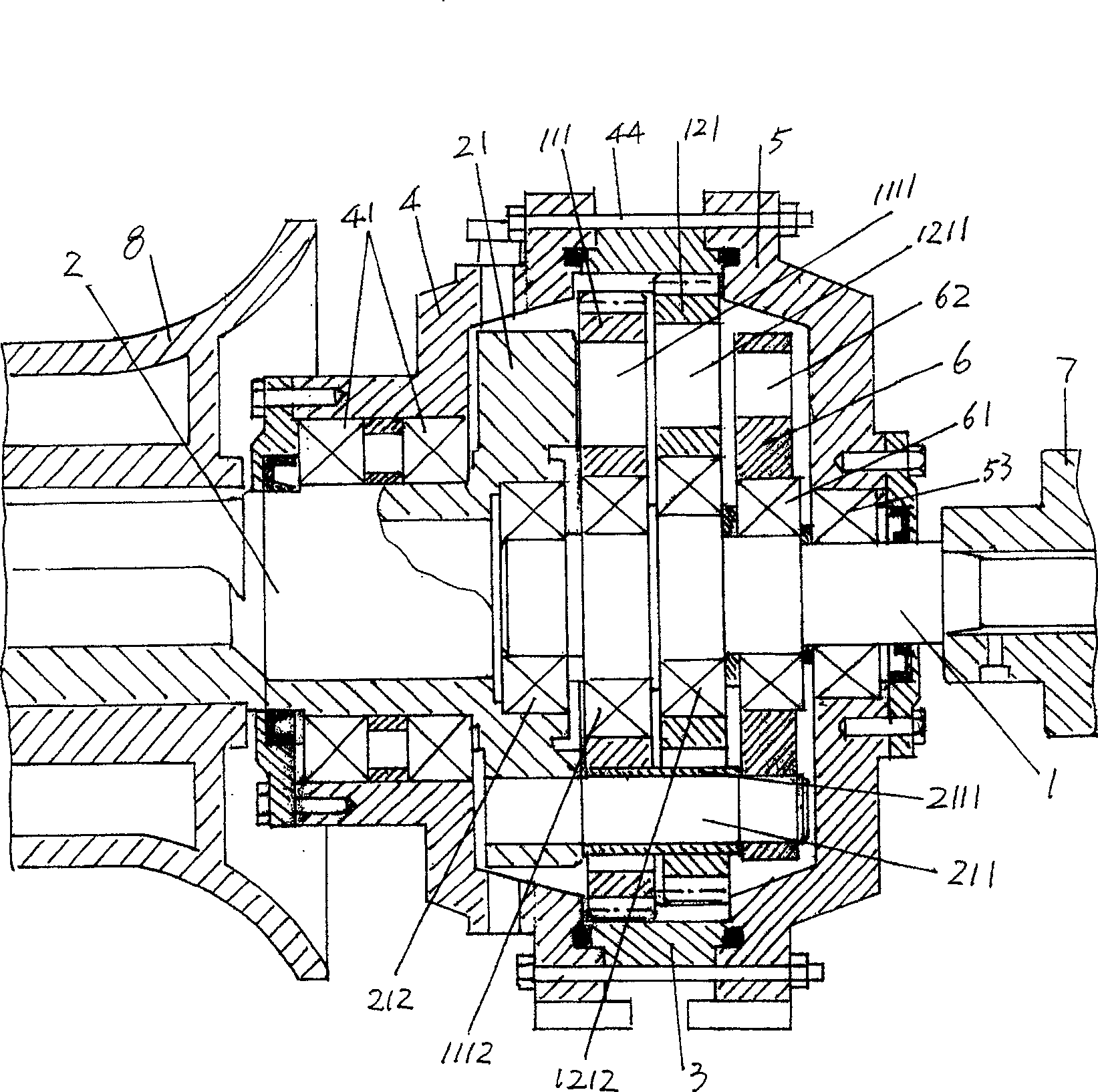
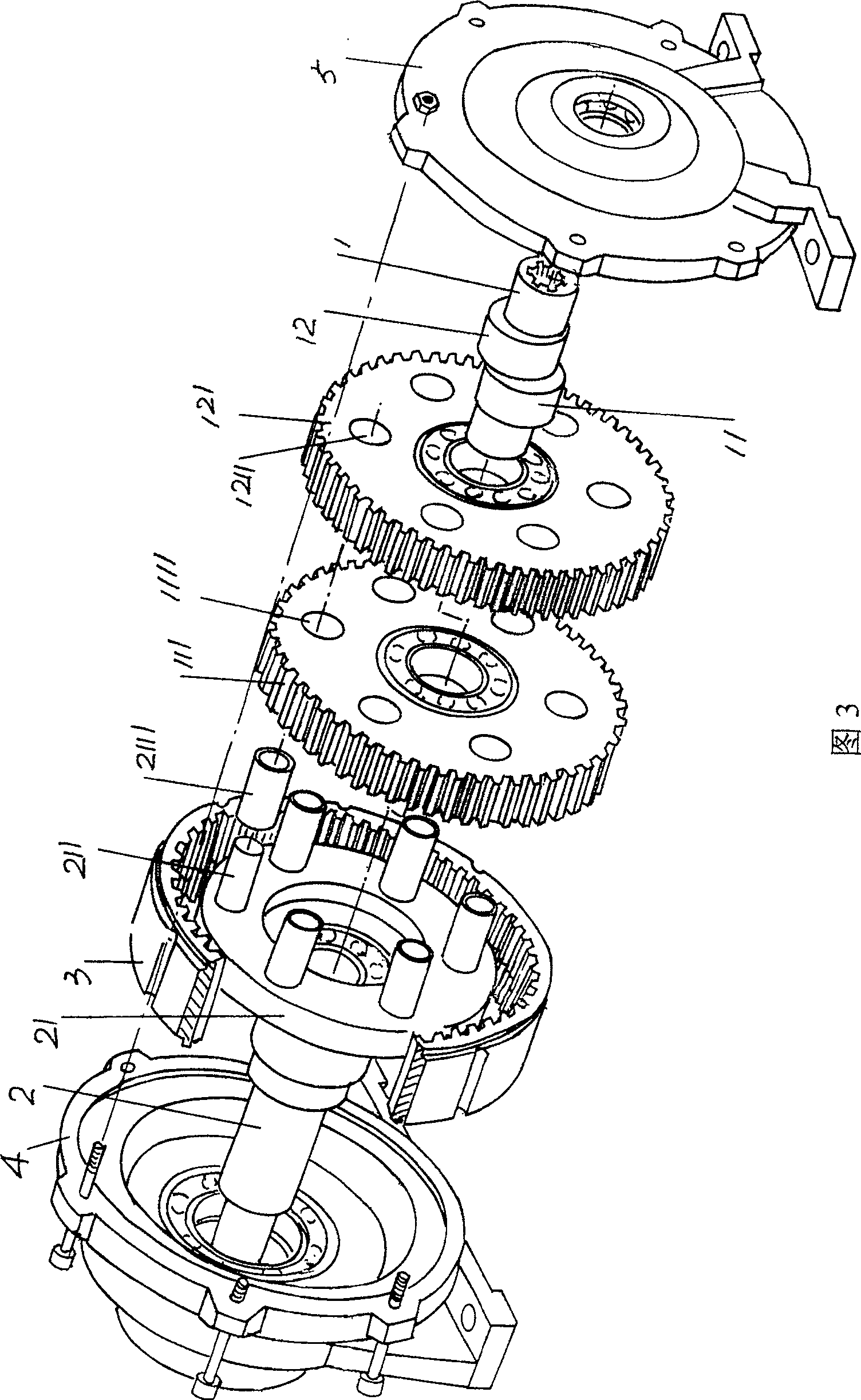
[0014] In Fig. 1, a camshaft 1, a pair of left and right cams 11, 12 are processed symmetrically in the middle of the camshaft 1, and left and right planetary gears 111, 121 are arranged on the left and right cams 11, 12 respectively. Specifically, the first and second bearings 1112 and 1212 are respectively installed in the center of the left and right planetary gears 111 and 121, and the left and right planetary gears 111 and 121 are set to On the left and right cams 11,12. A diaphragm 14 is expanded between the left and right cams 11, 12, which can keep a gap of the thickness of the diaphragm 14 between the gear faces of the left and right planetary gears 111, 121 to avoid mutual friction. The rims of the left and right planetary gears 111 and 121 are covered with teeth according to the required number. If the number of teeth is 51 teeth, the camshaft 1 rotates 360° for one turn, and the left and right planetary gears 111 and 121 only The transmission position of one tooth...


PUM


Abstract

The invention relates to a differential mechanism of entwisting milling device that includes a camshaft, a pair of left string quantity gear and right string quantity gear, an output shaft that one end has shaft disc connecting to left and right string quantity gear, a gear ring that keeps eccentricity with left and right string quantity gear and keeps concentricity with shaft disc, a pair of left and right end cover. The feature is that the gear wrist connects to a bearing disc after passing through left and right string quantity gear, and the right bearing disc locates on camshaft. The advantages of the invention are that it has entirely frame structure and gear wrist would not have distortion and broken, which is benefit for ensuring safety.

Description

technical field [0001] The invention relates to a differential mechanism of a winch mill, which is used for traction, line tightening, vertical rods, vertical towers, power equipment such as transformers and power distribution cabinets during construction and maintenance of power transmission and transformation lines, etc. It plays the role of changing the speed ratio on the winch mill of the special facility, and belongs to the technical field of electric power construction equipment. Background technique [0002] Before the differential mechanism of the winch involved in the Chinese patent CN2848809Y was released, because the gearbox of the winch commonly contained a differential and a speed change mechanism, that is, the differential mechanism and the speed change mechanism were jointly arranged in the gearbox , so there are four disadvantages. First, in order to configure the aforementioned two mechanisms in the gearbox, the volume of the gearbox must be appropriately in...

Claims


Application Information

Patent Timeline
Patent Type & Authority Patents(China)
IPC IPC(8): B66D1/22
Inventor 王炯秀
Owner 常熟市常福电力机具有限公司
Features
  • R&D
  • Intellectual Property
  • Life Sciences
  • Materials
  • Tech Scout
  • Unparalleled Data Quality
  • Higher Quality Content
  • 60% Fewer Hallucinations
Learn More