Multi-layer movable wall fluid resistance-reduction and propulsion device

A propulsion device and wall surface technology, applied in the direction of fluid flow, mechanical equipment, etc., can solve the problems of limited drag reduction effect, large channel friction resistance, high polymer price, etc., and achieve the effect of eliminating fluid resistance and reducing friction resistance

Inactive Publication Date: 2009-05-20
邹立松
View PDF6 Cites 3 Cited by
  • Summary
  • Abstract
  • Description
  • Claims
  • Application Information

AI Technical Summary

Problems solved by technology

After the establishment of the boundary layer theory, after years of development, drag reduction methods can be roughly divided into four categories according to different ways to reduce viscous drag. One is the method of locally changing the fluid near the boundary, such as hovercraft technology and air lubrication technology. The resistance potential is considerable, but the specific technology and technological measures to realize the replacement of viscous fluids with very different viscosities and specific gravity at all boundaries are still difficult to completely solve, and it is difficult to promote. At present, it is mainly used in the fields of transportation and mechanical engineering
The second type is to change and control the temperature of the boundary layer, or to change the flow velocity distribution of the laminar boundary layer through air suction and other measures to reduce viscous resistance. There are many researches and applications in the field of outflow such as aviation, which have been discussed in detail in a large number of monographs , its drag reduction effect is limited
The third type injects polymer dilute liquid into the wall area to reduce drag, which can be used for drag reduction of crude oil, water and other fluids, but polymers are expensive and prone to failure when subjected to shear force, and the drag reduction effect is limited
The fourth category is to use appropriate boundary materials (elastic materials) to make the boundary fully compliant, so that it is easy to generate dynamic responses, and vibrate with the TS wave fluctuation of the laminar boundary layer, which is developed by bionics research. However, its drag reduction effect is still limited
However, the reduction of shape resistance still basically stays in the aspect of exploring the streamlined line of the object. There is also a method to arrange a channel inside the drag-reduced object to connect the head and tail, so that the fluid can be discharged from the front to the rear through the channel, reducing the front and rear ends. The pressure difference reduces the viscous pressure resistance, but the channel friction resistance is relatively large, which affects the drag reduction effect
Another notable method is to let the boundary surface of the object move with the fluid movement. This early discovery has been verified by intuitive experiments, but later this method has not been widely used and is almost forgotten by people. And the drag reduction effect of its technical scheme is limited, so it has not attracted attention so far

Method used


Image

  • Multi-layer movable wall fluid resistance-reduction and propulsion device
  • Multi-layer movable wall fluid resistance-reduction and propulsion device
  • Multi-layer movable wall fluid resistance-reduction and propulsion device

Examples


Embodiment 1

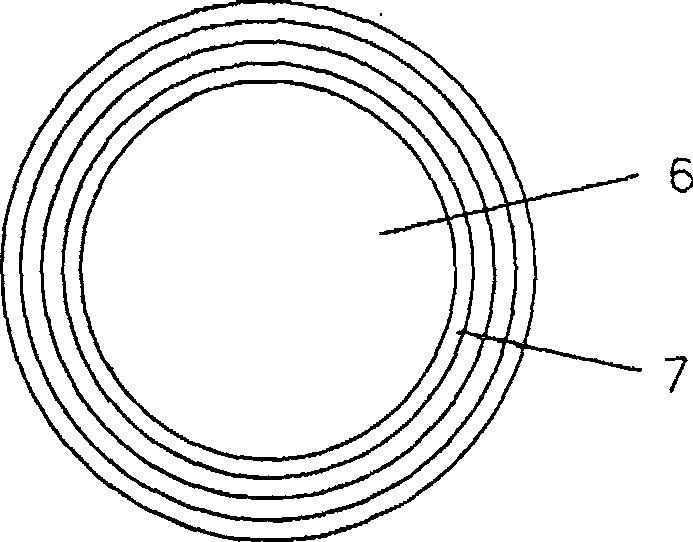
[0070] Figure 13 It is a schematic diagram of the division of oil pipeline drag reduction installation units and the positional relationship of each unit. If the pipe diameter is about 1100mm, the width of each unit is about 500~600mm. There are three layers, from the inside to the outside, they are one layer, two layer, and three layer. The average specific gravity of the movable wall is the same as that of petroleum or lubricating fluid, which can eliminate the sag caused by gravity. At the same time, it is pasted with a flexible composite magnetic strip to prevent or reduce its friction. Set up special joints at the joints of the pipelines, inside which are arranged driving drums, steering drums, etc., the movable wall surface steering method is the same Picture 9 As shown, the installation thickness of each movable wall (including its own thickness and the distance between the weights) is about 4mm, and the total thickness is about 4.4cm. It is equipped with a live button s...

Embodiment 2

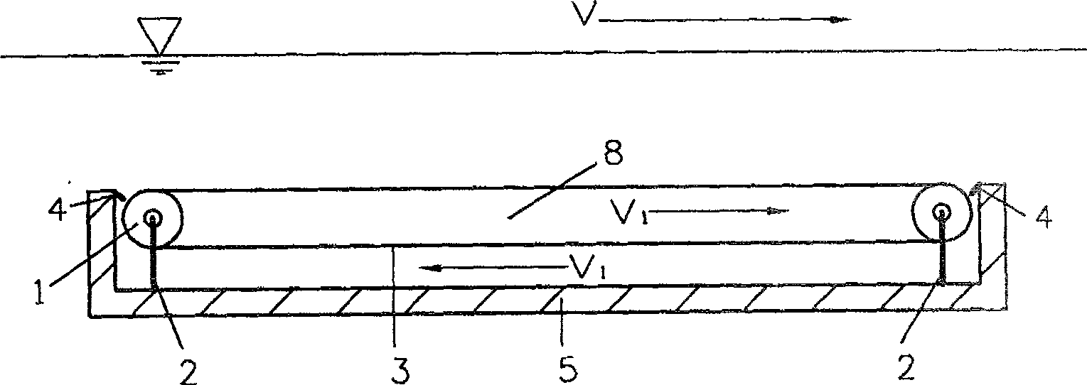
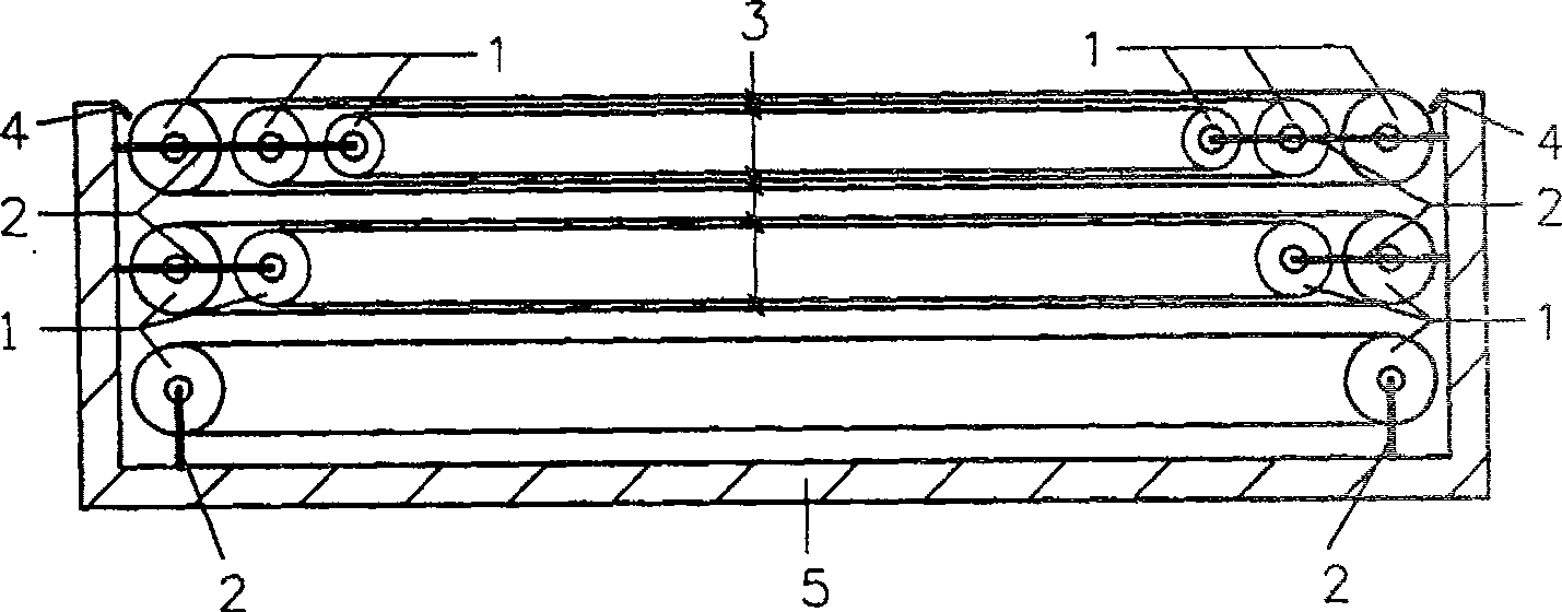
[0072] Install the device of the present invention in a certain level (or a small slope) water delivery channel to reduce the frictional resistance of water to the channel wall, Figure 14 It is a schematic diagram of the division of the installation unit. When the unit width is too wide, it can be added. The top is air, so there is no drag reduction device; five movable walls are installed along the channel wall, and each layer is one, two, three, three, and five movable walls in order from the canal wall, with 100 meters as one installation For the length of the unit, recessed grooves are arranged in the canal wall every 100 meters, and the driving drum, the steering drum and the contact mechanism between each layer are arranged in the groove. The movable wall surface of the adjacent outermost layer of each installation unit is provided with a live button seal of the present invention, and a multi-stage dynamic seal is provided between the end baffle of each unit and the movable...

Embodiment 3

[0074] The present invention is applied to the surface of the underwater floating body of a small waterplane surface ship to reduce fluid resistance: suppose the floating body is a cylinder with a diameter of about 1.5 meters, which is divided into three installation units. The positional relationship section of the three installation units is the same as that of the first embodiment. The cross-sectional schematic diagram is very similar, the difference is that the hexagon surrounded by three units is outside the cylinder, and each unit is about 1 meter wide. The longitudinal cross-section shows the same Figure 4 Basically the same, pay attention to the arrangement of the three units at the intersection of the head and tail. Two of them are turned at right angles at the head and tail, and multiple movable walls are arranged on the outside to reduce the resistance when crossing the top. Each unit is arranged five The heavy movable wall, and the secondary movable wall on the return...


PUM


Abstract

The invention provides a fluid drag-reducing and propelling device with plural layers of active wall surfaces, able to reduce resistance to fluid, arranging one to plural layers of active wall surfaces able to circularly rotate on the surface of an object in the flowing direction of the fluid, where one to multiple active wall surfaces are arranged in the space formed by each layer of active wall surface, all the active wall surfaces moves with the fluid, reducing their relative speed to the fluid so as to reduce frictional resistance and energy consumption; by applying driving force to make the moving speeds of the active wall surfaces greater than that of the fluid, it can produce propelling force, able to reduce pressure difference between the two ends of the object and thus reducing shape resistance and making the frictional resistance disappear. And it can be widely applied to various drag reducing occasions of fluid.

Description

Technical field [0001] The present invention relates to a device that reduces fluid resistance (including frictional resistance, viscous pressure resistance and similar resistance) and has a propulsion function (pressurization function). Background technique [0002] For a long time, when people are looking for ways to reduce fluid resistance, their attention has been only focused and limited to the shape, that is, exploring the streamlined aspect of objects. The current air drag reduction design of high-speed trains, missiles, and automobiles is still at this stage. After the creation of the boundary layer theory, after years of development, the drag reduction methods can be roughly divided into four categories according to different ways to reduce the viscous resistance. The first category is the method of locally changing the fluid near the boundary, such as hovercraft technology, air lubrication technology, and its reduction. The resistance potential is considerable, but the ...

Claims


Application Information

Patent Timeline
Patent Type & Authority Patents(China)
IPC IPC(8): F15D1/00
Inventor 邹立松
Owner 邹立松
Why Eureka
Try Eureka