Reusable parameter module model building method for space continuous deformation MEMS

A modeling method, parametric technology, applied in chemical instruments and methods, electrical components, electrical digital data processing, etc.

Inactive Publication Date: 2009-06-10
NORTHWESTERN POLYTECHNICAL UNIV
View PDF1 Cites 0 Cited by
  • Summary
  • Abstract
  • Description
  • Claims
  • Application Information

AI Technical Summary

Problems solved by technology

[0005] In order to overcome the disadvantage that the prior art cannot be used to describe MEMS devices with space continuous deformation behavior characteristics, the present invention proposes a method for establishing a reusable parameterized component model for space continuous deformation MEMS devices

Method used


Image

  • Reusable parameter module model building method for space continuous deformation MEMS
  • Reusable parameter module model building method for space continuous deformation MEMS
  • Reusable parameter module model building method for space continuous deformation MEMS

Examples


Embodiment 1

[0021] DETAILED DESCRIPTION OF THE PREFERRED EMBODIMENTS Implementation Example 1: A method for establishing a component model of an electrostatically actuated microbeam.

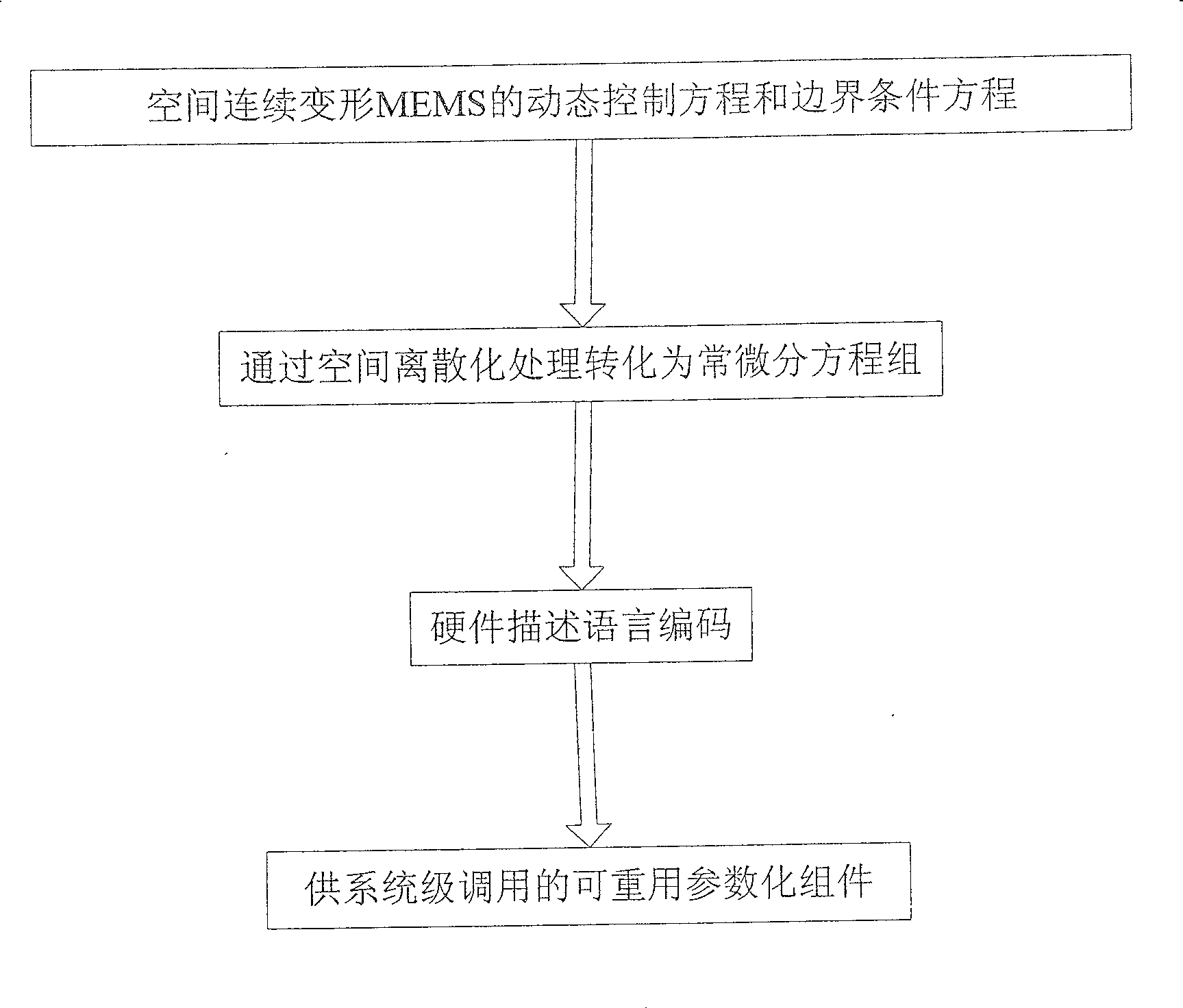
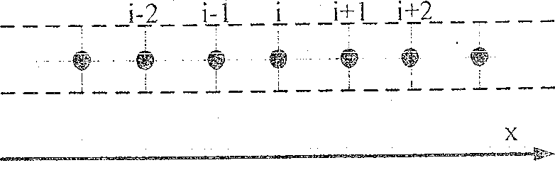
[0022] Step 1: Determine the dynamic control equations and boundary condition equations describing each energy domain and its coupling state according to the energy domains and coupling modes involved in the electrostatically actuated microbeam.

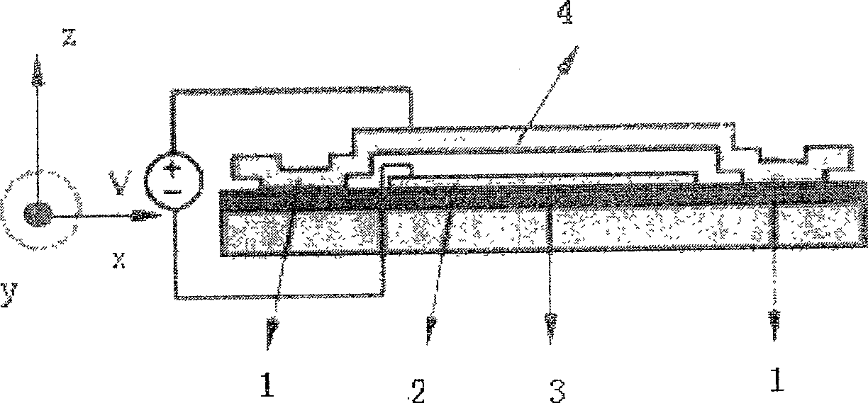
[0023] attached figure 2 It is a schematic diagram of a double-terminal fixed electrostatically actuated microbeam structure, which is a common structure in MEMS systems and is widely used in RF switches, micro accelerometers, pressure sensors and other devices. When a voltage V is applied between the upper and lower electrodes, the upper electrode is deformed under the action of electrostatic attraction, and the magnitude of the electrostatic force received by each point on the beam is related to the deflection of this point. The axis of the beam when it is not...

Embodiment 2

[0042] Implementation example 2: a method for establishing a component model of a capacitive pressure sensor.

[0043] Step 1: Determine the dynamic control equations and boundary condition equations describing each energy domain and its coupling state according to the energy domains involved in the capacitive pressure sensor and their coupling methods.

[0044] attached Figure 5 It is a schematic diagram of the structure of a capacitive pressure sensor, and its elastic element is composed of a diaphragm fixed around it. The deformation equation of the diaphragm after being subjected to external pressure and electrostatic pressure can be described as:

[0045] D ∂ 4 w ∂ x 4 + 2 D ∂ 4 w ...


PUM


Abstract

A modeling method of reusable parameterized component for space continuous deformation MEMS includes confirming each dynamic control equation and boundary condition equation of MEMS device, carrying out space discretization on dynamic control equation and converting said control equation to be constant-differential equation set, utilizing hardware description language of analog and mixed signal to carry out coding for realizing function description, plotting schematic diagram of MEMS device and connecting said diagram with code to form MEMS device being called in system modeling and in simulation analysis.

Description

technical field [0001] The invention relates to a method for establishing a model of a micro-electro-mechanical system (MEMS) device, belonging to the field of computer-aided design (MEMS CAD) of a micro-electro-mechanical system. Background technique [0002] With the improvement of integration, the demand for MEMS system-level design will become more and more urgent. System-level design focuses on modeling and performance simulation of the entire microsystem (including mechanical structures, circuits, and multi-domain coupling components, etc.). Due to the difficulty and complexity of related work, how to establish a model that can accurately express device behavior and realize reusable parametric component models has become a key issue, which is crucial for the development of MEMS CAD technology and the improvement of MEMS design efficiency and R&D level. [0003] Among the existing MEMS system-level modeling methods, the nodal analysis method can establish a parameteriz...

Claims


Application Information

Patent Timeline
Patent Type & Authority Patents(China)
IPC IPC(8): G06F17/50B81C5/00B81C99/00
Inventor 马炳和张承亮吕湘连苑伟政
Owner NORTHWESTERN POLYTECHNICAL UNIV
Why Eureka
Try Eureka